3 – entering i2c bootloader, 2 – bootloader operation, Entering i2c bootloader – Maxim Integrated DS4830 Optical Microcontroller User Manual
Page 171: Bootloader operation, Ds4830 user’s guide
DS4830 User’s Guide
171
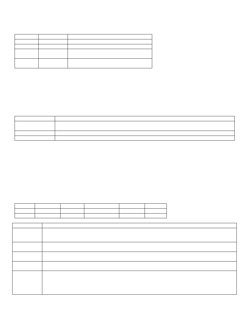
Table 22-2 JTAG Bootloader Status Bits
Bits 1:0
Status
Condition
00
Reserved
Invalid condition.
01
Reserved
Invalid condition
10
Loader-Busy
ROM Loader is busy executing code or
processing the current command.
11
Loader-Valid
ROM Loader is supplying valid output data
to the host in current shift operation.
22.1.3
– Entering I2C Bootloader
The DS4830 also has built-in functionality that allows bootloading over I
2
C. Bootloading via I
2
C allows the system to
update the firmware using only the I
2
C bus without JTAG or firmware intervention. To access the bootloading function,
slave address 34h is used. This slave address is setup by hardware and cannot be changed through firmware. As long
as the Slave I
2
C port is enabled, which is the default, the DS4830 will always respond to this slave address without any
firmware interaction required. This address should not be used for any purpose other than the special bootloading
features. Table 22-3 details the special functions that can be performed using slave address 34h.
Table 22-3. Special Functions of Address 34h
Command byte
Action
F0h
Sets the I2C_SPE bit in the I2C_SPB register to enable bootloading via I
2
C. This bit will not be
cleared on device reset.
BBh
Executes a reset of the DS4830 when an I
2
C Stop is received.
All other bytes
The I2C_SPE bit in I2C_SPB is cleared. The DS4830 will NACK this byte.
To enter I
2
C bootloader, the host must first write slave address 34h with data F0h and then issue a stop command. When
the stop command is received, the I
2
C _SPE bit will be set. The DS4830 must then be reset. This can be done using
either the /RST\ pin or by using the I
2
C self reset. To do an I
2
C self reset, the host needs to write slave address 34h with
data BBh. Upon receiving an I
2
C stop, a reset will be performed.
22.2
– Bootloader Operation
Once in bootloader mode, the JTAG and I
2
C interfaces both use the same commands. How these commands are
implemented will be different between the two interfaces. Table 22-4 shows an example command and parameters. The
next two sections will detail how to implement these commands using either the JTAG or I
2
C interface.
Table 22-4 Example Bootload Command
Byte(s)
Command
Data In
NOP
Data Out
Return
Input
Command
Data In
00h
00h
00h
Output
X
X
X
Data Out
3Eh
Byte Name
Description
Command
All bootloader commands begin with a single command byte. The upper four bits of this command byte
define the command family (from 0 to 15) and the lower four bits define the specific command within that
family.
Data In
Data bytes that are input to the bootloader that are required for the command. The number of Data In
bytes varies for each command. Some commands do not require any Data In bytes.
NOP
The NOP byte is only used for JTAG mode. This is a byte of 00h that is clocked into TDI, while TDO is
ignored.
Data Out
Data Out is any data that is returned by the bootloader. The number of Data Out bytes varies for each
command. Some commands do not output any Data Out bytes.
Return
A return value of 3Eh is output by the bootloader at the start of first command and following the
successful completion of every command thereafter. If the Return byte is read prior to 3Eh being loaded
by the bootloader, the read will return the data that is currently in the shift register. The value 3Eh is only
loaded into the shift register once. Any subsequent reads will return invalid data. In JTAG bootload
mode, status bits will tell when ROM loader is sending valid 3Eh.