Section 6 – digital-to-analog converter (dac), 1 – detailed description, Section 6 – Maxim Integrated DS4830 Optical Microcontroller User Manual
Page 42: Digital-to-analog converter (dac), Detailed description
DS4830 User’s Guide
42
SECTION 6
– DIGITAL-TO-ANALOG CONVERTER (DAC)
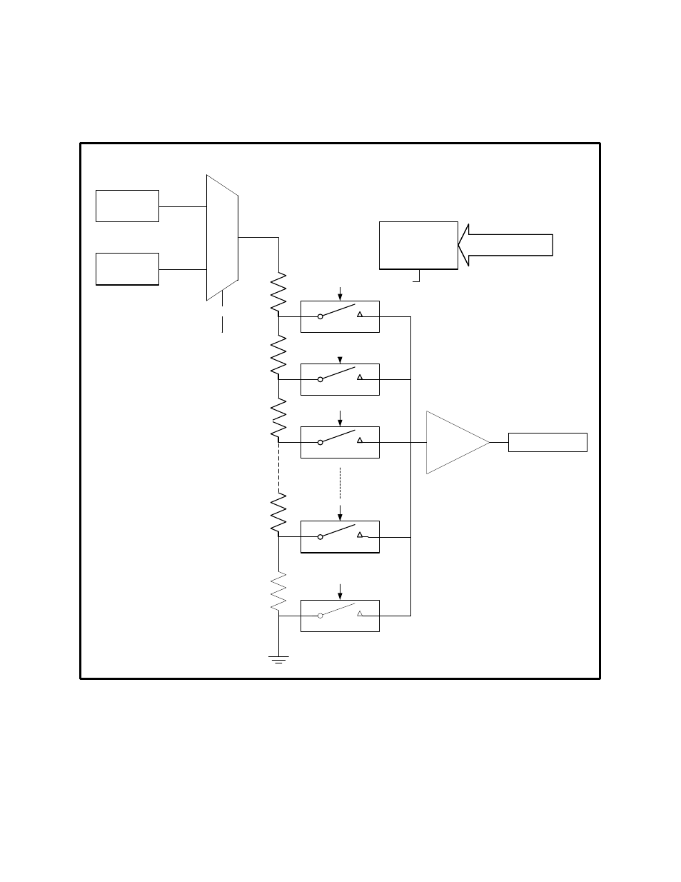
The DS4830 contains eight 12-bit digital-to-analog converters (DACs). Each DAC has a voltage output buffer. Each DAC
can independently select between a 2.5V internal reference and external reference at REFINA pin for DAC0 to DAC3 and
at REFINB pin for DAC4 to DAC7.
12-Bit
Decoder
Data Bus
To DAC Switches
R
R
R
R
R
DAC Output
Internal
Reference
External
Reference
Ref Selection
4095
1
0
4094
4093
MUX
10b
01b
Output
Buffer
Figure 6-1: DAC Functional Block Diagram
6.1
– Detailed Description
The DS4830 DAC architecture consists of a resistor string with switches and decoder followed by a voltage buffer. The
DS4830 has eight independent DACs, each having the same architecture. As shown in Figure 6-
1, each DAC’s reference
is software selectable. Each DAC is independently configurable using the DAC configuration and DAC data registers. The
DAC configuration register (DACCFG) provides the facility to enable or disable DACs independently and select the
reference. Each DAC can be configured for either an internal (2.5V) or an external reference.