Configuring dlci parameters (figure 7-4, item d), Frame relay dlci configuration screen 1 -12, Configuring dlci parameters (figure 7-4 , item d) – Cabletron Systems 1800 User Manual
Page 80: At figure 7-4 an d, when prompted, enter a, The default is
7-12
SmartSwitch 1800 4. 0 User G uide, Rev 01
Configuring DLCI Parameters (Figure 7-4, Item D)
To configure DLCI parameters (listed in
), press
[D]
at
and, when
prompted, enter a
DLCI ID:
16–991
. (The default is
16
.) This will display a screen
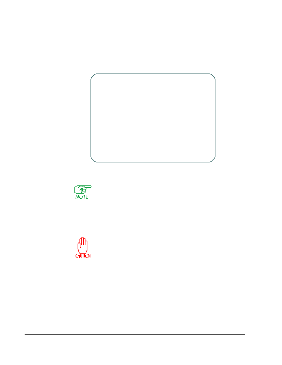
Figure 7-6 Frame Relay DLCI Configuration Screen 1
Pressing
[F4]
at this or the subsequent screen (
) will delete the
DLCI rate control and backup configuration. (The port will not be deleted
unless
[F4]
is pressed at one of the higher-level port screens—
and
.)
Note that the DLCI is not yet deleted. If it was created solely for frame
relay backup, it will remain in existence until the node is rebooted. If the
DLCI was created when configuring an IP, IPX, or LLC2 interface, it will
remain until that interface is deleted and the node is rebooted.
If a primary DLCI is brought down, then deleted from the
database while the backup is operational, end-to-end connec-
tivity over the backup will fail. For this reason, a primary DLCI
should never be deleted. (If there is a need to delete the DLCI, it
should first be re-configured so that it is not part of a frame relay
backup situation.)
Nod e Name=n ode_xyz
Frame Relay DLC I C onfiguration (s creen 1 of 2)
*
RLP
0
*
Port
7
*
DLCI
16
A
Committed In formation Rate (I n)
2000
B
Committed Burst Size (In)
2000
C
Excess Burst Size (In)
1000
D
Committed In formation Rate (Out)
2000
E
Committed Burst Size (Ou t)
2000
F
Excess Burst Size (Ou t)
1000
G BECN Recovery C ount
8
H Ou tgoin g DLC I Priority
0
I
DLCI Backup C onfiguration
Option: