Port assignment worksheet, Port assignment worksheet -2, Physical port locations -2 – Cabletron Systems 1800 User Manual
Page 26
2-2
SmartSwitch 1800 4. 0 User G uide, Rev 01
Port Assignment Worksheet
The port options on Voice models of SmartSwitch 1800 differ from those on data-only
models. Information on both is provided here, along with worksheets that allow you
to fill in pertinent information that you will use to configure the software database.
Naturally, you should fill in only the table that applies to your model type.
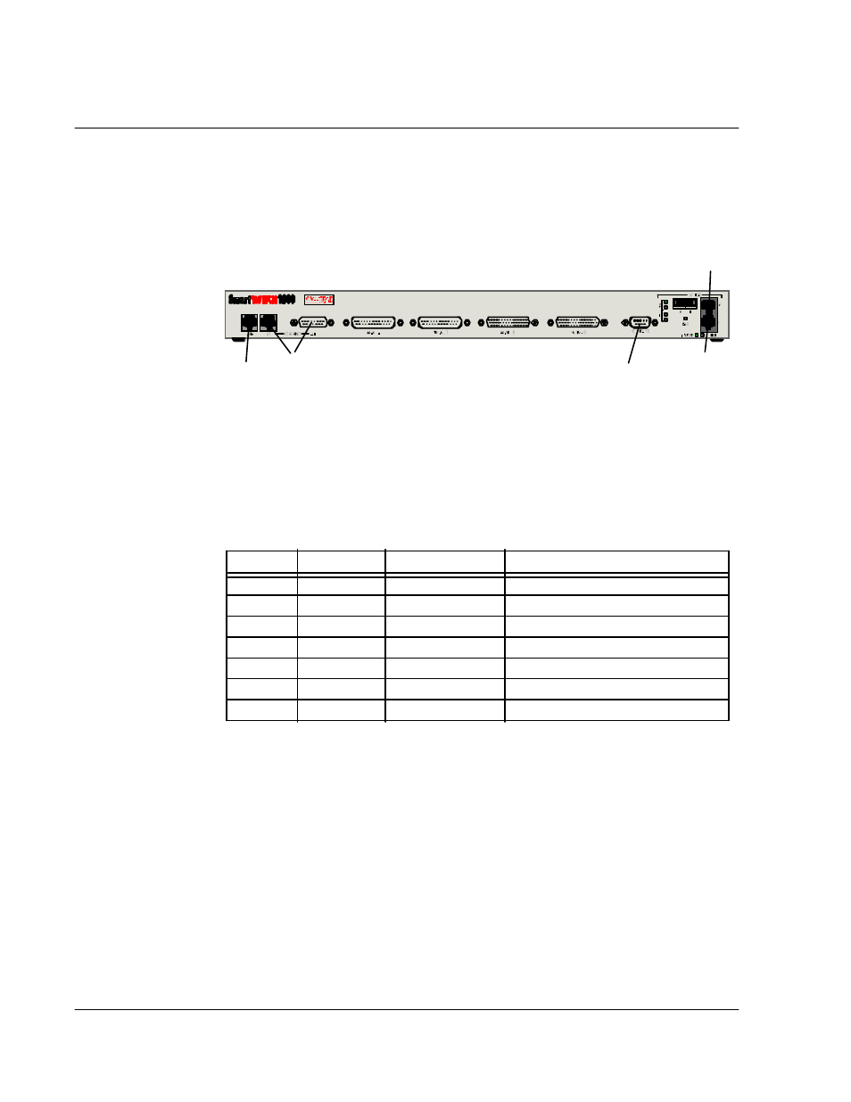
Figure 2-1 Physical Port Locations on Voice Models
Table 2-2 lists all possible physical ports on Voice models of SmartSwitch 1800.
1
Physical interface, as described below.
Port 0 is RS-232.
Port 1 must be either RS-232 or DSU.
Ports 2 and 3 are determined by the attached cable: V.35, RS-232, or RS-449.
Ports 4 and 5 are Voice.
Each cable is physical DTE (male connector) or DCE (female connector). Add a
T
or
C
to
the interface type to record this information. (This does not apply to a Voice, DSU, or LAN
port.)
2
The protocols that can be assigned to ports depend on the model of SmartSwitch 1800 and
the options that were purchased. All possible protocols are listed below:
Ports 0–3: Frame relay, X.25, SDLC, BSC Interactive, BSC Batch, Async.
Ports 4, 5: Voice.
LAN Port: IP, IPX, Bridge, LLC2.
Note that the LAN protocols (IP, IPX, Bridge, LLC2) are also assigned to physical frame
relay ports via interface records that map the protocols to the physical ports.
Table 2-1 Port Assignments for Voice Models
Port
Interface
1
Protocol
2
Connected Device
0
RS-232
1
2
3
4
n/a
Voice
5
n/a
Voice
LAN
n/a
Voice 1
Optional
CSU/DSU Port
LAN Port
WAN 0
WAN 1
WAN 2
WAN 3
Console Port
Voice 2