Mapped dlci num ber, Bl ocked port flag, Causes the logical port to be disabled – Cabletron Systems 1800 User Manual
Page 106: Or enabled, Table 8-2 logical port parameters
8-14
SmartSwitch 1800 4. 0 User G uide, Rev 01
1
Once this parameter has been selected for the first time,
1
becomes the default value.
2
1–7
if modulo 8,
1–127
if modulo 128. Changing this parameter will disable the link only
if the new value changes the modulus.
3
0
means the parameter is not used.
4
Maximum Packet Size
values are
128, 256, 512, 1024, 2048
, &
4096
.
Default Packet
Size
values are all of the above plus
16, 32
, &
64
. If X.25 will be run over this port, do
not configure a size greater than
2048
. If
4096
is specified, additional X.25 and frame
headers can make the frame too large.
2048
will not cause a problem, since larger frames
will simply be split, then re-assembled at the destination.
Mapped DLCI Number
is the Data Link Connection Identifier, which links the logical port to a logical con-
nection on the physical frame relay port. It must match the DLCI configured on the
device at the other end of the local (rather than end-to-end) connection.
Make sure no more than one of any interface type (logical port,
frame relay IP/IPX/LLC2 interface, or frame relay Bridge port)
is assigned the same DLCI.
Also make sure this DLCI is not configured as a Frame Relay
Backup DLCI or as part of an intra-nodal frame relay PVC.
Blocked Port Flag
causes the logical port to be disabled (
Y
) or enabled (
N
) (only if the physical port is
also enabled) at node IPL. The port will remain in that state until this parameter is
changed or an on-line enable (
[B], [B], [C]
from the Main Menu) or disable (
[B], [B], [A]
from the Main Menu) is performed.
16–4096
4
128
2–7
7
1–7
2
see explanation
none
0–15 characters
none
(sec)
1–600
60
(sec)
1–600
180
(sec)
1–600
60
(sec)
1–600
60
0–99
0
0–99
0
0–99
0
CUG Parameters
Y/N
N
0–99
0
Y/N
N
Y/N
N
See explanation
n/a
See explanation
n/a
See explanation
n/a
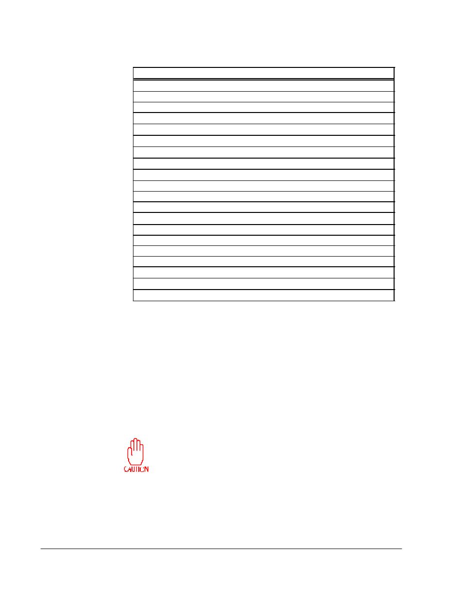
Table 8-2 Logical Port Parameters
Parameter
Valid Values
Default Value