Cabletron Systems 1800 User Manual
Page 407
Voice Configuration Ref erence Informat ion
C-15
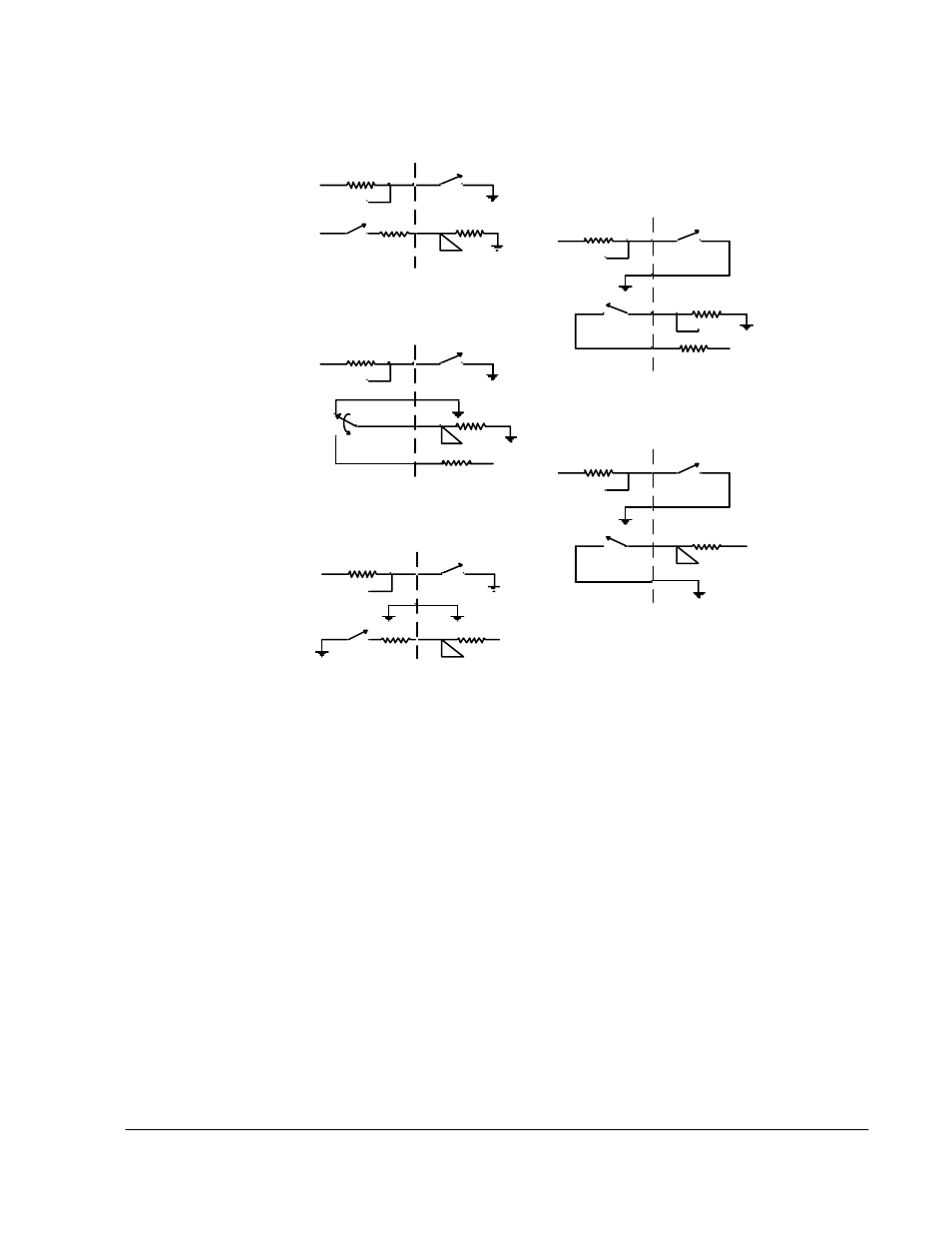
Figure C-9 E&M Signaling Types
The illustrations in this figure are abstracted from the specifications to show the
essential components of the signaling circuitry. In this figure, the symbol V refers to
battery voltage, which can be -25 Vdc to -65 Vdc, and is usually (nominally) -48 Vdc.
Each of the illustrations in the figure show the PBX's E&M interface on the left, and
the corresponding tie line equipment interface on the right.
Type I
With the Type I interface the tie line equipment generates the "E" signal to the PBX
by grounding the "E" lead. The PBX detects the "E" signal by sensing the increase in
current through a resistive load (this is indicated in the figure by the unconnected node
branching from the right side of the "E" resistor). Similarly, the PBX generates the
"M" signal by sourcing a current to the tie line equipment, which detects it via a
resistive load. The Type I interface requires that the PBX and tie line equipment share
a common signaling ground reference. This can be achieved by connecting signal
ground from the PBX to the SG lead (pin 8) of the RJ45 connector.
V
E
M
V
P BX
V
E
PBX
SG
V
M
SB
V
E
P BX
V
SB
M
S G
V
E
PBX
SG
V
M
SB
V
E
M
P BX
V
SG
Tie Line
E q u ip m e n t
Tie Line
E q u ip m e n t
Tie Line
Equipm ent
Tie Line
Equipme nt
Tie Line
Equipm ent
Ty pe I
Type II
Type III
Type IV
Type V