Port assignments -2, Table 2-2, Table 2-2 port assignments for data-only models – Cabletron Systems 1800 User Manual
Page 27
Getting St arted
2-3
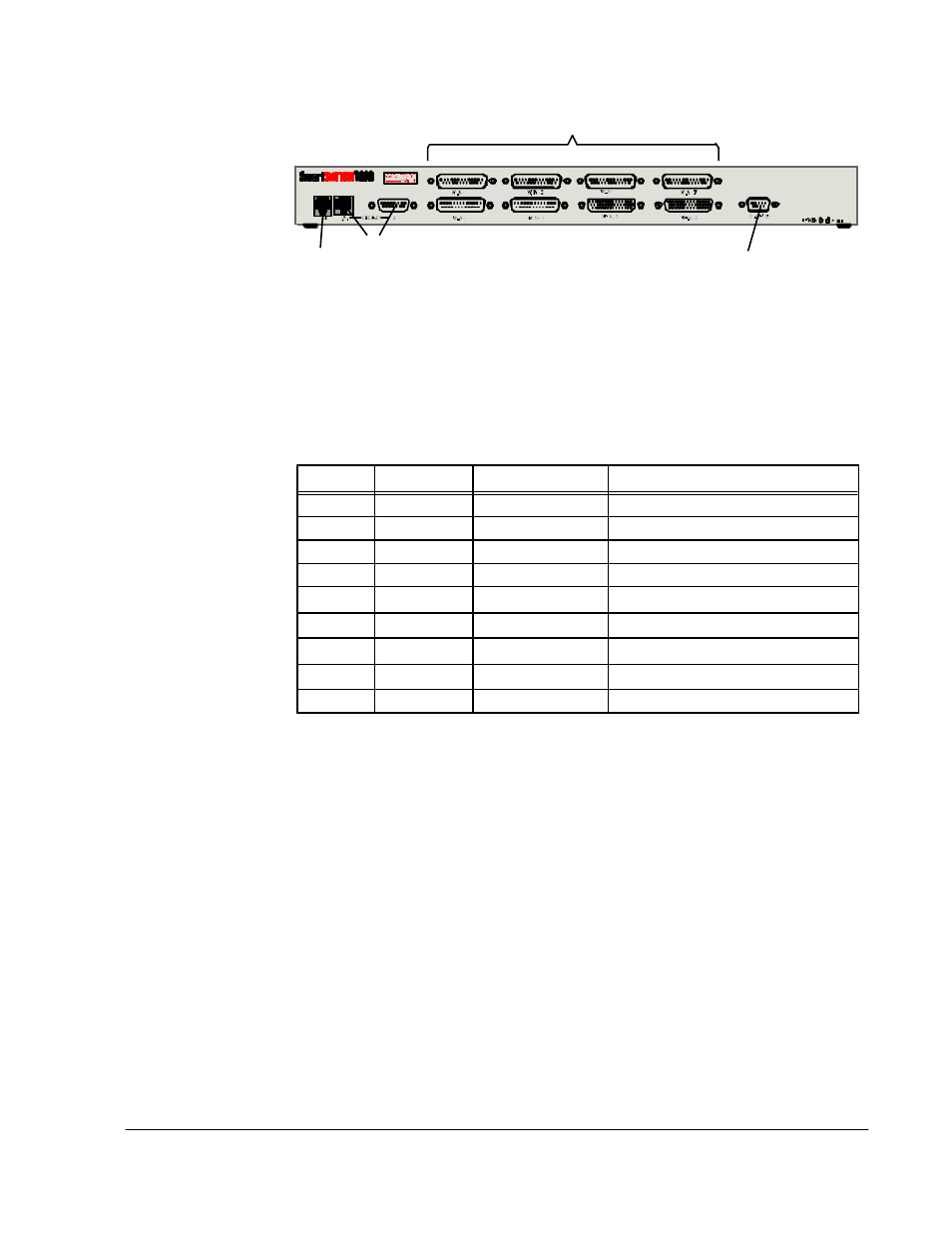
Figure 2-2 Physical Port Locations on Data-Only Models
Table 2-2 lists all possible physical ports on data-only models of SmartSwitch 1800.
1
Physical interface, as described below.
Port 0 is RS-232.
Port 1 must be either RS-232 or DSU.
Ports 2 and 3 are determined by the attached cable: V.35, RS-232, or RS-449.
Ports 4–5 exist only if an optional expansion card is installed, and are determined by the
type of card: V.35, RS-232, or RS-422 (which supports RS-449 interfaces, and X.21 by
special order).
Each cable is physical DTE (male connector) or DCE (female connector). Add a
T
or
C
to
the interface type to record this information. (This does not apply to a DSU or LAN port.)
2
The protocols that can be assigned to ports depend on the model of SmartSwitch 1800 and
the options that were purchased. All possible protocols are listed below:
Ports 0–7: Frame relay, X.25, SDLC, BSC Interactive, BSC Batch, Async.
LAN Port: IP, IPX, Bridge, LLC2.
Note that the LAN protocols (IP, IPX, Bridge, LLC2) are also assigned to physical frame
relay ports via interface records that map the protocols to the physical ports.
3
Only if the optional expansion card is installed.
Table 2-2 Port Assignments for Data-Only Models
Port
Interface
1
Protocol
2
Connected Device
0
RS-232
1
2
3
4
3
5
3
6
3
7
3
LAN
n/a
Optional
CSU/DSU Port
LAN Port
WAN 4
WAN 5
WAN 6
WAN 7
Console Port
Ports 4–7 are on an optional expansion card
WAN 0
WAN 1
WAN 2
WAN 3