Template 13: boring cycle, dwell/feed out, Chapter 31 – Rockwell Automation 8520-MUM 9/Series CNC Mill Operation and Programming Manual Documentation Set User Manual
Page 846
Using Transfer Line Cycles
Chapter 31
31-44
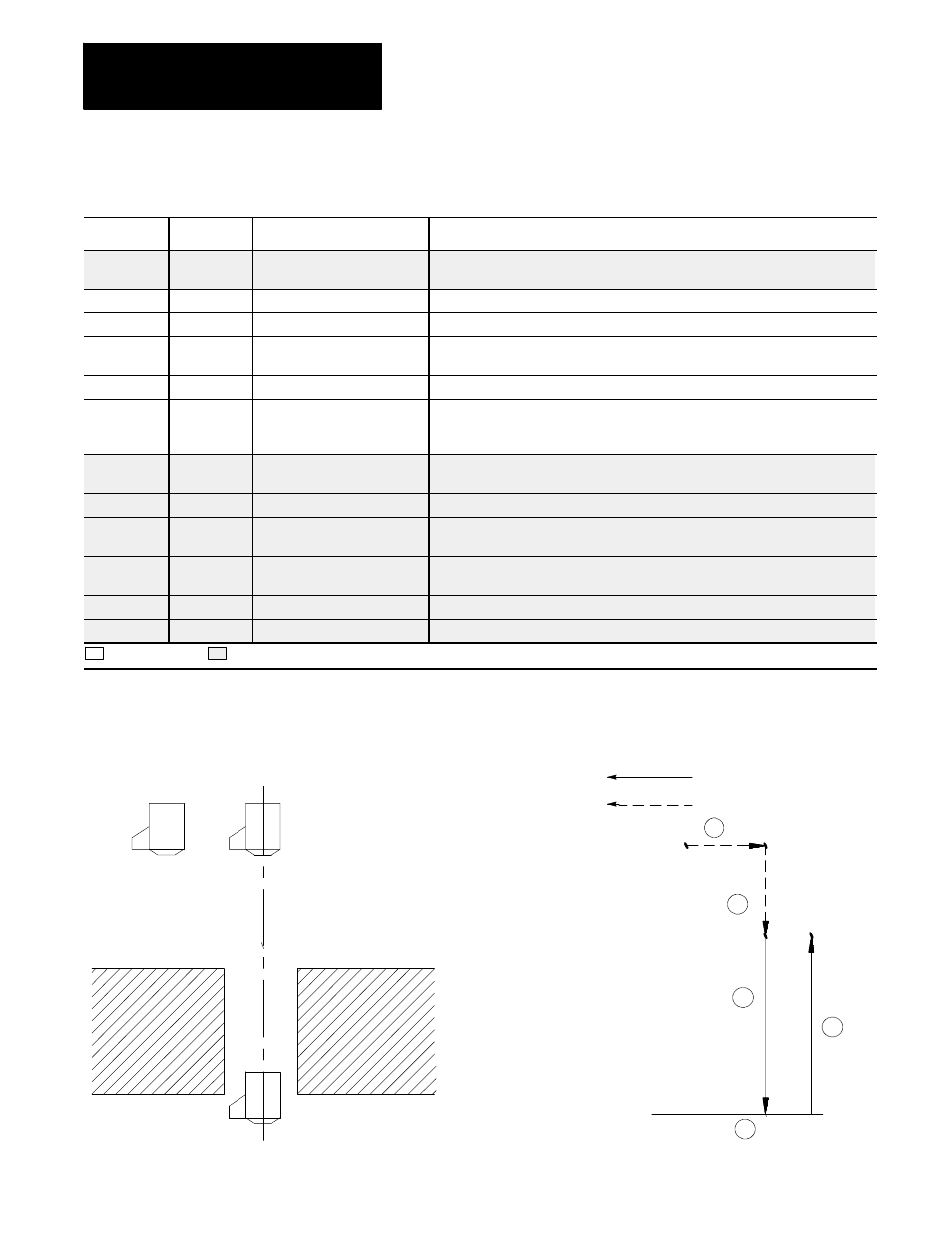
Template 13: Boring Cycle, Dwell/Feed Out
Letter
Paramacro
Label
Description
G
500
G90/91
G-codes G90 or G91 for absolute or incremental modes. At this time only absolute
mode, G90, is available.
X,Y
501, 502
HOLE POSITION X, Y
The location to which the tool moves before it begins a boring operation.
X
503
DEPTH OF HOLE
The location to which the tool bores into the part.
R
504
CLEAR POSITION
The location that the tool retracts to after an operation. It is completely free of the
part. This also known as the R plane.
X,Y
505, 506
RETURN POSITION X, Y
The location where the controls starts and stops a cycle.
F
507
FEEDRATE
The feedrate for drilling/boring operations, and all moves represented by the solid
lines in the QuickView screens. This is also the maximum feedrate for operations
that use adaptive depth.
P
508
AMOUNT OF DWELL
The amount of time the axis pauses before it retracts from the hole; measured in
seconds.
X
509
TOOL CHANGE POSITION
The location the control moves to so that a tool change may be performed.
I
510
HARD STOP SENSE ZONE
Once it reaches this location, the control knows to expect a hard stop before
reaching the hole bottom.
I
511
ADAPTIVE DEPTH
INCREMENT
The amount of distance that the control will increment the tool into the part during an
adaptive depth operation.
M
512
M03/M04
The M--code used to turn the spindle clockwise or counter-clockwise.
S
513
SPINDLE SPEED
The speed of the spindle. Measured in revolutions per minute.
Required entry
Optional entry
Figure 31.16
Boring Cycle, Dwell/Feed Out
Dwell
R
1
2
3
4
5
Cutting feedrate
Maximum cutting feedrate
Depth of Hole
Clear Position
Hole Position
Return
Position