Rockwell Automation 8520-MUM 9/Series CNC Mill Operation and Programming Manual Documentation Set User Manual
Page 681
Skip, Gauge, and Probing Cycles
Chapter 27
27-7
Tool Gauging Application Example
A typical application for these G-codes in determining tool offsets would
execute as follows:
1.
When the control executes the G37 block, the triggering device
moves towards the tool using the axis specified in the block.
2.
When the control receives the appropriate skip signal through PAL,
axis motion stops.
3.
The control records the position when the skip signal is received. It
determines the difference by subtracting the position specified with
the axis word in the G37 block from this position. The difference is
then added to, or replaces the value in the appropriate geometry or
wear table for the currently active tool offset number.
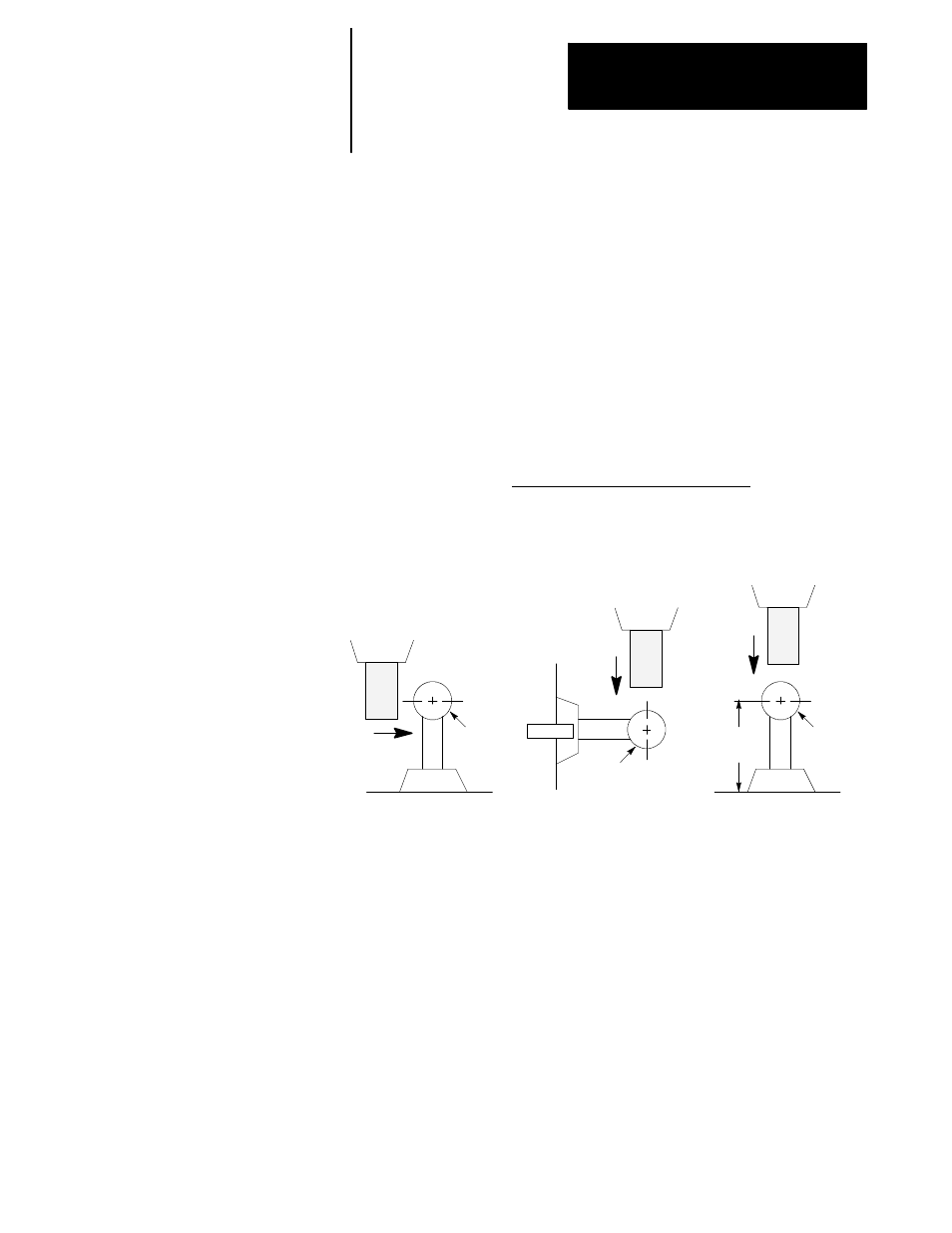
Figure 27.1
Typical Tool Gauging Configurations
Probe
Probe
radius
Tool
Probe
Probe
radius
Tool
Probe
Probe
radius
Probe
length
Tool
Case 1
Case 2
Case 3
Figure 27.1 illustrates 3 typical tool gauging configurations. All 3 cases
assume that the probe is at a known, fixed point on the machine.
Note that in Case 1 the tool radius is being gauged, while in Case 2 the tool
length is being gauged. In both of these cases, only the probe tip radius is
significant to the control in calculating the offset adjustment.
In Case 3, the tool length is being gauged, and both the probe radius and
the probe length are significant to the control’s offset adjustment
calculations.
Important: The tool gauging configuration Case 3 depicted in Figure 27.1
is not recommended due to the risk of probe damage.