Spindles – Rockwell Automation 8520-MUM 9/Series CNC Mill Operation and Programming Manual Documentation Set User Manual
Page 437
Chapter
17
17-1
Spindles
This chapter describes how to program spindles:
Information about:
On page:
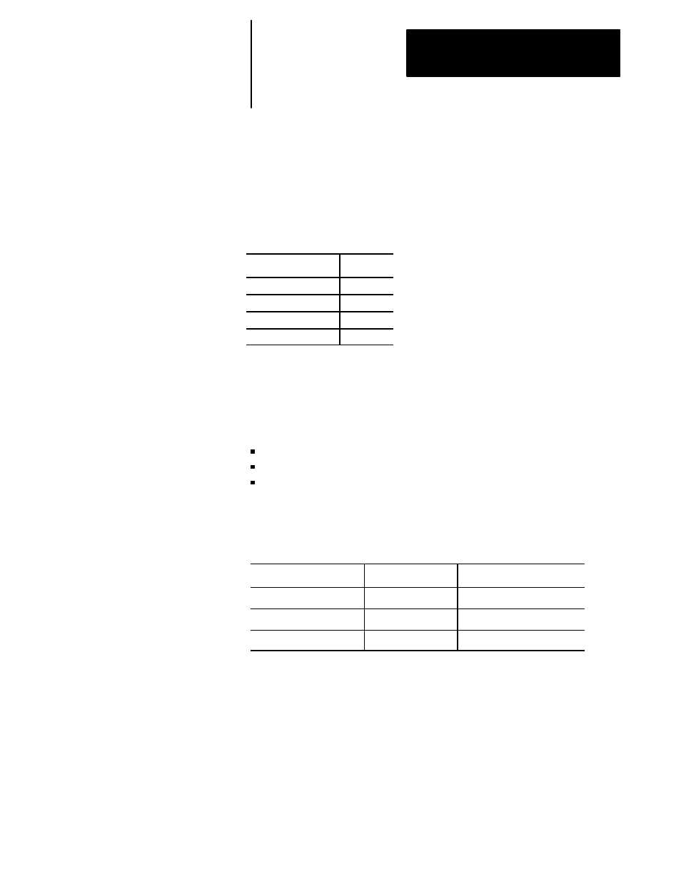
Controlling Spindle
17-1
Spindle Orientation
17-3
Spindle Direction
17-5
Synchronized Spindles
17-6
The G12 code is used to program the active controlling spindle for features
and modes requiring spindle operation. The G12 code is modal. Only one
spindle may be the controlling spindle. Only the 9/260-9/290 control uses
more than one spindle. All other spindles are auxiliary spindles.
G12.1 — Spindle 1 Controlling
G12.2 — Spindle 2 Controlling
G12.3 — Spindle 3 Controlling
Table 17.A shows the spindle capabilities of each control.
Table 17.A
Spindle Capabilities of the 9/Series Controls
Type of 9/Series Control
Number of Spindles
Spindle Type
9/230, 9/240
1
Primary
9/260
2
Primary, Auxiliary 2
9/290
3
Primary, Auxiliary 2, Auxiliary 3
Spindles 1, 2, and 3 must be configured in AMP, and the associated spindle
parameters must be set properly to provide for the required spindle
functions.
For systems with no spindle configured, simulated spindle feedback is
provided for the controlling spindle. This allows all control features that
require spindle feedback, i.e., IPR feedrate, threading, CSS, to simulate the
feedback from a spindle even through the AMPed system configuration
contained no spindle. The default is 4000 counts-per-rev device.
17.0
Chapter Overview
17.1
Controlling Spindle
(G12.1, G12.2, G12.3)