Rockwell Automation 8520-MUM 9/Series CNC Mill Operation and Programming Manual Documentation Set User Manual
Page 788
Chapter 30
Using a 9/Series Dual--processing System
30-20
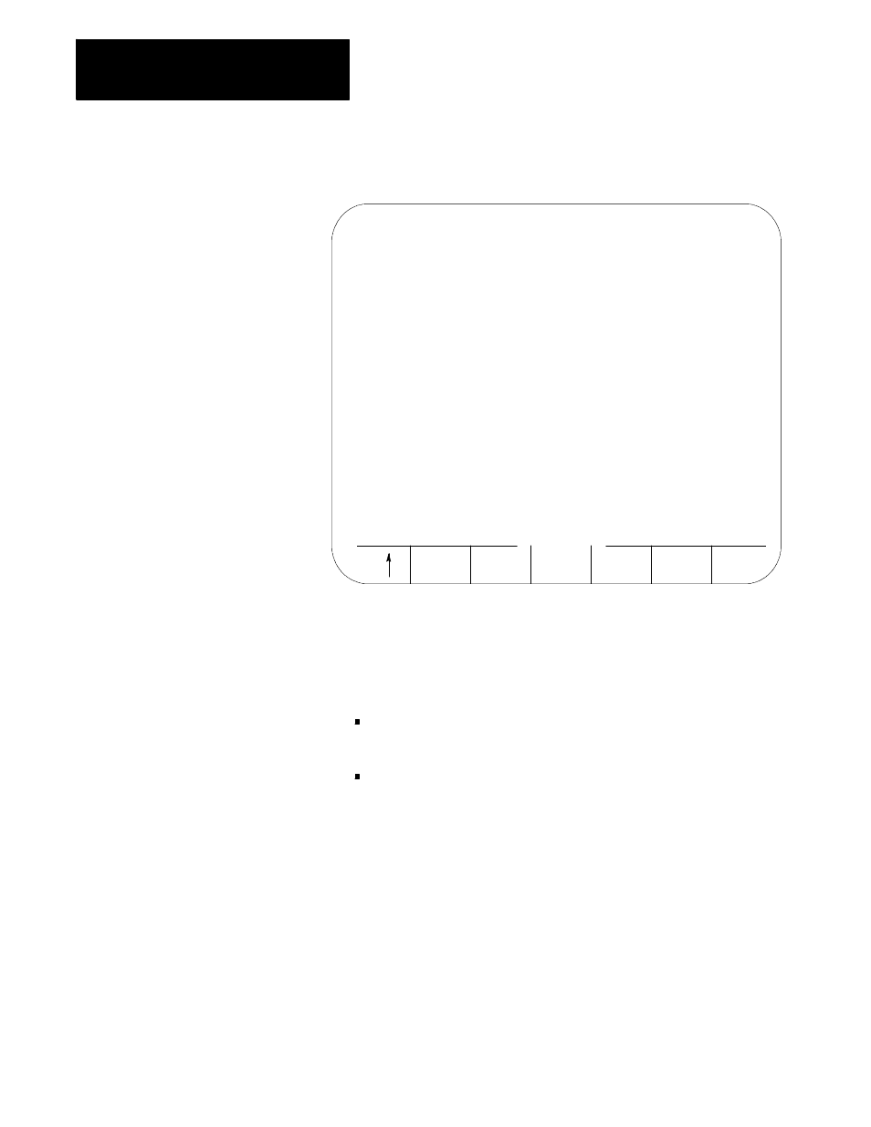
Figure 30.7
Interference Checking Data Table
SEARCH
NUMBER
REPLCE
VALUE
ADD TO
VALUE
MORE
ZONES
BACKUP
INTERF
INTERFERENCE TABLE
PAGE
1
OF 32
TOOL NO
AREA 1
AREA 2
*1
[INCH]
[INCH]
X PLUS
1.5000
1.5000
X MINUS
-.5000
-1.0000
Z PLUS
1.5000
6.0000
Z MINUS
0.0000
1.5000
4.
Select a process. Refer to the system installer’s documentation for
details on selecting a process, or press the [PROC SELECT] key.
5.
Select a boundary number to enter by using one of these two
methods. Press:
the {MORE ZONES} softkey, or press the [
• ] key while holding
down the [SHIFT] key.
the {SEARCH NUMBER} softkey. Enter the desired boundary
number to search for and press the [TRANSMIT] key.
This boundary number is typically the same as the tool geometry
number (H-word) that is active when the tool and/or fixture is being
controlled. Refer to your system installer’s documentation for details
on which tool or fixture corresponds to which interference boundary
number (1-32).
6.
Use the up or down cursor keys to move the block cursor to the
interference area parameter to be changed. The selected field appears
in reverse video.
7.
If necessary, change the measurement units by using MDI. Units
currently used in the table are determined by the current mode of the
process (G20 inch or G21 metric).