1 manual mirror image – Rockwell Automation 8520-MUM 9/Series CNC Mill Operation and Programming Manual Documentation Set User Manual
Page 414
Axis Motion
Chapter 14
14-38
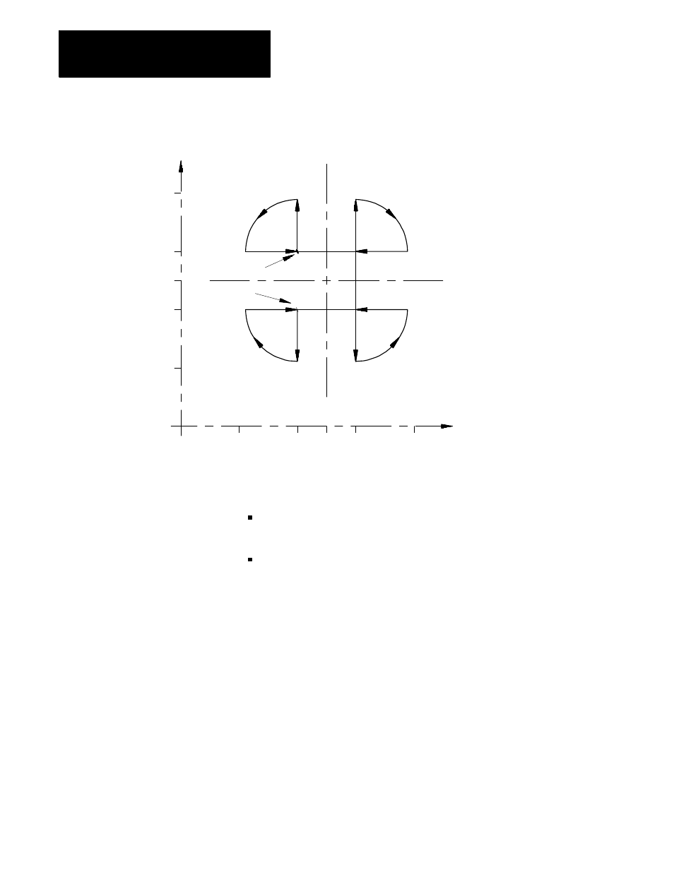
Figure 14.19
Results of Programmable Mirror Image Example
120
90
75
60
30
Start point
End point
0
120
90
75
60
30
Y
X
When the mirror image function is active on only one of a pair of axes
used in circular interpolation or cutter compensation, the control:
executes a reverse of programmed G02/G03 arcs. G02 becomes
counterclockwise and G03 become clockwise.
activates a reverse of programmed G41/G42 cutter compensation. G41
becomes tool right and G42 becomes tool left.
In addition to the programmable mirror image function, the control may
also be equipped with an optional manual mirror image switch, installed by
the system installer, that will activate the manual mirror image function.
The manual mirror image function may also be activated by using the
{FRONT PANEL} softkey.
The manual mirror image features differ from the programmable mirror
image feature in that when using the manual mirror image feature the
location of the mirrored plane is fixed along the selected axis in the current
work coordinate system. This means that the mirror plane is parallel to the
selected axis and passes through the zero point of the currently active work
coordinate system.
14.5.1
Manual Mirror Image