Rockwell Automation 8520-MUM 9/Series CNC Mill Operation and Programming Manual Documentation Set User Manual
Page 277
Introduction to Programming
Chapter 10
10-3
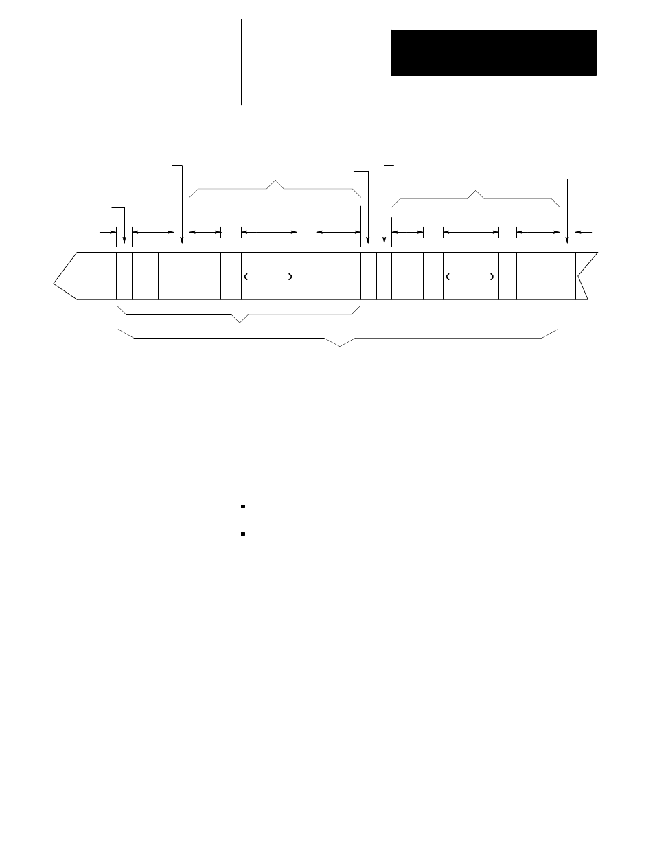
Figure 10.2
Tape Configuration (Program End = % (ASCII), ER (EIA))
E
O
B
Program start code
Leader
section
Tape start
code
Part program
Program
end code
Tape end
code
1 foot
space
O100
Program
name
(opt)
O101
Program
name (opt)
Program
end code
Part program
%
Comment
(opt)
E
O
B
Comment
(opt)
Program start code
ER
or
%
or
ER
%
or
ER
Typical single program tape
Typical multi-program tape
%
This tape format should conform to the variable block length format
specified by EIA standard RS-274D.
The control automatically recognizes EIA or ASCII during input when it
reads the first EOB code from the tape.
(1) Tape Start (Rewind, Stop Code)
The tape start code, indicating the beginning of a tape, is designated with:
% character ---- ASCII format
ER ---- EIA format
This code must be on the tape if programming a tape rewind code (M30,
M99) in the part program. In other cases (M02, %), it is not necessary to
have this code on the tape. Any tape punched from the control has the tape
start code.
(2) Leader Section
The information between the tape start and the program start is called the
tape leader section. The leader section is simply a tape indexing section.
On punched tape, the holes punched in the leader section can be configured
to show alphanumeric characters. The control ignores information within
the leader section and does not perform a parity check on this information.
Important: A program start code must not appear within the leader
section. If the program start code appears, the control starts reading
information and assumes that it is the part program. This causes parity
errors or “nonsense” codes read in by the control.