Rockwell Automation 8520-MUM 9/Series CNC Mill Operation and Programming Manual Documentation Set User Manual
Page 295
Introduction to Programming
Chapter 10
10-21
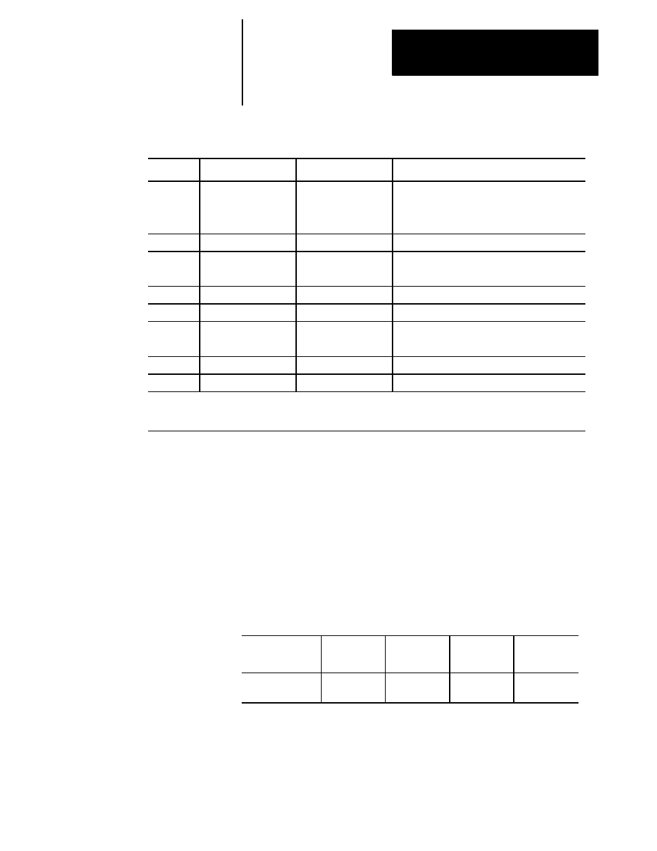
Table 10.B
Word Formats and Descriptions
Address
Valid Range Inch
Valid Range Metric
Function
S
5.3
5.3
Spindle rpm function
5.3
5.3
Spindle Orient
4.3
3.3
CSS
T
6.0
6.0
Tool selection function
U
8.6
8.5
Incremental axis name (Lathe A only)
5.3
5.3
Length of dwell in G04 and fixed cycles.
V
8.6
8.5
Incremental axis name (Lathe A only)
W
8.6
8.5
Incremental axis name (Lathe A only)
X
8.6
8.5
Main axis (AMP assigned)
5.3
5.3
Length of dwell in G04
Y
8.6
8.5
Main axis (AMP assigned)
Z
8.6
8.5
Main axis (AMP assigned)
1
Important: The formats in this table indicate the maximum number of digits left and maximum number of digits right of
the decimal point for each word. In many cases they are not valid together since the control allows a maximum of 8 total
digits. Refer to the system installer’s manual for specific formats.
The maximum programmable value accepted by the control is 99,999,999.
The minimum is .000001 inch or .00001 mm. However, the actual range
of programmable values depends on specifications determined by the
system installer.
By using AMP to establish the format of numeric values for words, the
system installer sets the “programming resolution,” for axis motion, that is,
the smallest programmable distance of axis motion.
Table 10.C
Programming Resolutions
Formats as set in
AMP
_.3
_.4
_.5
_.6
Corresponding
Resolution
0.001
0.0001
0.00001
0.000001
Refer to the system installer’s documentation for the programming
resolutions and ranges in a specific system.
10.4.1
Minimum and Maximum
Axis Motion (Programming
Resolution)