Rockwell Automation 8520-MUM 9/Series CNC Mill Operation and Programming Manual Documentation Set User Manual
Page 724
Paramacros
Chapter 28
28-24
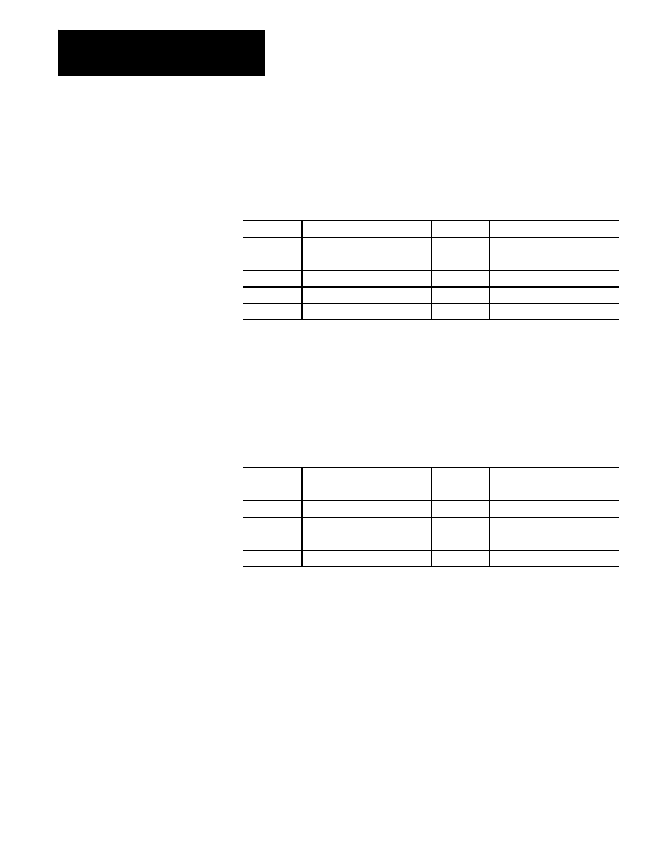
#5021 to 5032
Coordinates of Commanded Position
These parameters are read-only. They correspond to the current
coordinates of the cutting tool. These are the coordinates in the work
coordinate system.
5021
Axis 1 coordinate position
5027
Axis 7 coordinate position
5022
Axis 2 coordinate position
5028
Axis 8 coordinate position
5023
Axis 3 coordinate position
5029
Axis 9 coordinate position
5024
Axis 4 coordinate position
5030
Axis 10 coordinate position
5025
Axis 5 coordinate position
5031
Axis 11 coordinate position
5026
Axis 6 coordinate position
5032
Axis 12 coordinate position
The system installer determines in AMP the name (or word) that is used to
define the axis.
#5041 to 5052
Machine Coordinate Position
These parameters are read-only. They correspond to the coordinates of the
cutting tool in the machine (absolute) coordinate system.
5041
Axis 1 coordinate position
5047
Axis 7 coordinate position
5042
Axis 2 coordinate position
5048
Axis 8 coordinate position
5043
Axis 3 coordinate position
5049
Axis 9 coordinate position
5044
Axis 4 coordinate position
5050
Axis 10 coordinate position
5045
Axis 5 coordinate position
5051
Axis 11 coordinate position
5046
Axis 6 coordinate position
5052
Axis 12 coordinate position
The system installer determines in AMP the name (or word) that is used to
define the axis.
Position data for the absolute position of an adaptive depth probe is
invalid.