Fig. 3-84 – SkyTrak 6042 Service Manual User Manual
Page 85
3.39
Model 6042 Legacy
Origin 7/02
Boom
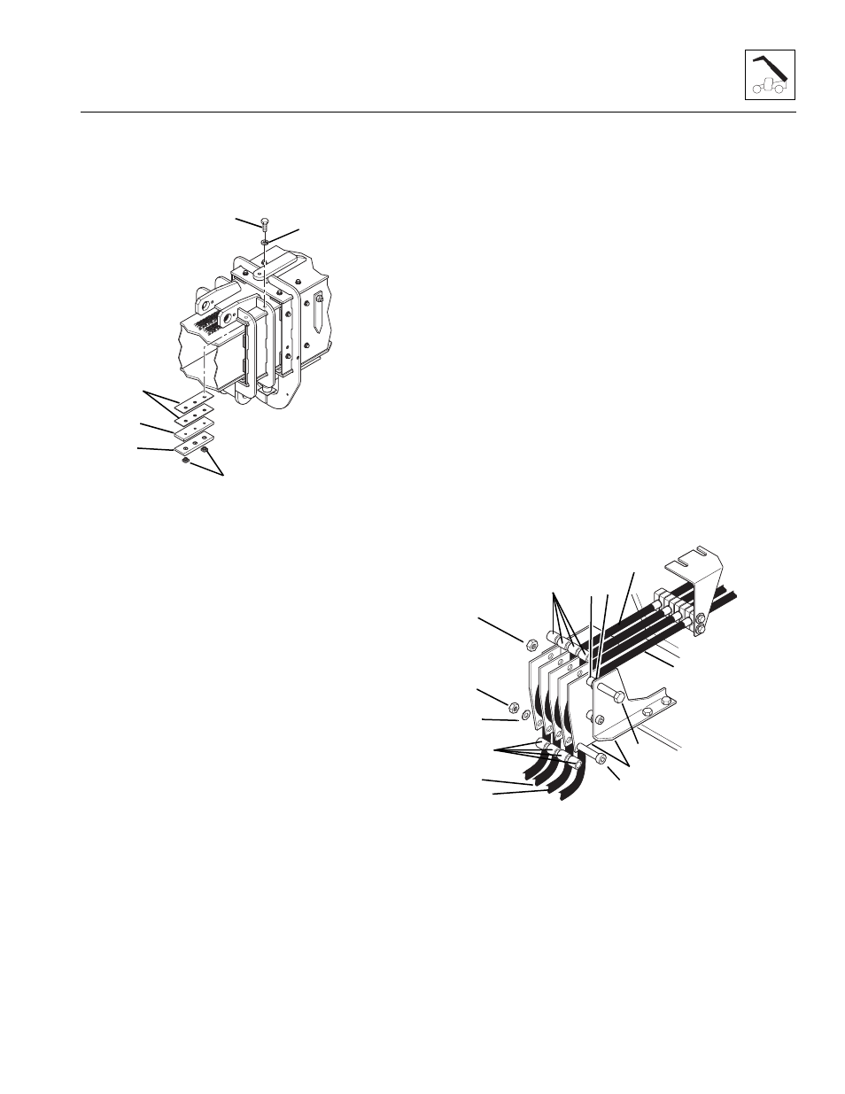
c. Torque all wear pad mounting capscrews to
31 ±3 lb-ft (42 ±4 Nm).
d. Fill all wear pad cavities with a good grade of
lithium-base EP grease.
Figure 3- 84 Front Intermediate Wear Pads
20. Pull the male ends of the hoses out the rear of the
inner boom. Stretch the hoses out straight behind
the vehicle.
21. Assemble the hoses to the hose reel at the back of
the boom:
IMPORTANT: Keep the hoses in the same order as they
come from the hose clamps. DO NOT allow the hoses to
cross.
a. Remove the 1/2-13 elastic locknut (Fig. 3-85, 1)
from the upper retaining capscrew (2). While
pulling the capscrew out, catch the spacers (3)
from between the plates as the capscrew is
removed. Pull the capscrew out far enough to
place the hoses around the hose reel. Make sure
that spacer (4) and washer (5) remain in place
between the inside two plates (6) of the hose reel
assembly.
Place the left side auxiliary hydraulic hose
(Fig. 3-85, 7) into the left position on the hose reel.
Place the left side attachment tilt hose (8) into the
second position from the left on the hose reel.
Place the right side attachment tilt hose
(Fig. 3-85, 9) into the second position from the
right on the hose reel.
Place the right side auxiliary hydraulic hose
(Fig. 3-85, 10) into the right position on the hose
reel.
Note: ALWAYS replace elastic-lined nuts with new
elastic-lined nuts to help ensure proper fastening.
b. Insert the retaining capscrew (Fig. 3-85, 2) back
through the plates of the hose reel, inserting the
spacers (3) back in position between the plates
as the capscrew is inserted. Make sure that
spacer (4) and washer (5) remain in place
between the inside two plates (6) of the hose reel
assembly. Secure the retaining capscrew in
place with a new 1/2-13 elastic locknut (1).
Tighten the elastic locknut securely.
c. Remove the 3/8-16 elastic locknut (Fig. 3-85, 11)
and 3/8" flat washer (12) from the lower retaining
shoulder bolt (13). While pulling the shoulder bolt
out, catch the spacers (14) from between the
plates as the shoulder bolt is removed. Place the
attachment tilt hoses and the auxiliary hydraulic
hoses around the hose reel.
d. Insert the shoulder bolt (Fig. 3 -85, 13) through
the plates of the hose reel, inserting the
spacers (14) back in position between the plates
as the shoulder bolt is inserted. Place the 3/8"
flat washer (12) onto the shoulder bolt and
secure in place with a new 3/8-16 elastic
locknut (11). Tighten securely.
Figure 3- 85 Assemble Hoses to Hose Reel
MA10,0420
1
2
4
5
6
3
MA10,0580
1
13
2
3
7
8
9
10
11
12
14
4 5
6