SkyTrak 6042 Service Manual User Manual
Page 298
Hydraulic System
8.66
Model 6042 Legacy
Origin 7/02
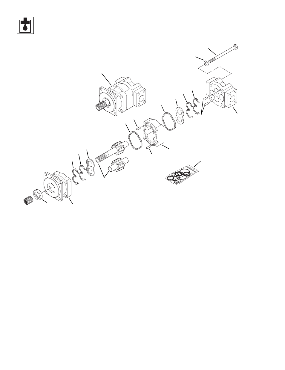
Figure 8-32 Hydraulic System Pump
11. Install the remaining thrust plate (Fig. 8 -32, 11) with
channel (9) and back-up (10) seals over the gears so
that the groove in the thrust plate will face away from
the gear housing (4). The flat side of the seal should
face up with the relief groove facing the outlet side of
the housing.
12. Place the gear housing (Fig. 8-32, 4) over the gear
set. Align the pump housings according to the
alignment mark made during disassembly. Insert the
dowel pins (7) in the gear housing into the holes in
the SEC housing (2). DO NOT pinch the square “R”
seal (8). Gently tap the gear housing around the
edges with a soft hammer as needed to further
engage the dowels and to bring the housings
together for final seating.
13. Place the Port End Cover (PEC) housing (Fig. 8-32, 3)
over the gear set. Align the pump housings according
to the alignment mark made during disassembly. Insert
the dowel pins (7) in the PEC housing with the holes in
the gear housing (4). DO NOT pinch the square “R”
seal (8). Gently tap the PEC housing in the center with
a soft hammer as needed to further engage the dowels
and to bring the housings together for final seating.
14. Install the four capscrews (Fig. 8-32, 5) and washers
(6) that secure the pump housings (2, 3 and 4)
together. Tighten the capscrews in a criss-cross
pattern to evenly draw the housing sections together.
Rotate the drive shaft to verify that there is no
binding within the pump. After the capscrews are
tight and there is no internal binding, torque the
capscrews to specification in a criss-cross pattern.
Refer to the torque specification chart in Section 2.3,
Torques.
MT1410
1
2
3
4
5
6
7
8
9
10
11
12
13
14
7
7
11
9
10
8