Drive shaft disassembly, Caution – SkyTrak 6042 Service Manual User Manual
Page 169
5.17
Model 6042 Legacy
Origin 7/02
Axles, Drive Shafts, Wheels and Tires
4. Disconnect the battery negative (-) cable at the
battery negative (-) terminal, to prevent the engine
from starting accidentally.
5. The drive shaft assembly is a balanced assembly.
Mark the yoke and axle, transmission, and the shaft
and slip yoke so that these components can be
returned to their original positions when reinstalled.
Yokes at both ends of the drive shaft must be in the
same plane to help prevent excessive vibration.
6. Remove the four hex-head capscrews (Fig. 5-14, 1)
and two straps (2) securing the bearing cross to the
transmission input shaft flange.
7. Remove the four hex-head capscrews (Fig. 5-14, 3),
four lockwashers (4) securing the flange yoke (5) to
the engine output flange.
8. Remove the drive shaft assembly (Fig. 5-14, 6).
Figure 5- 11 Drive Shaft Removal
5.4.4
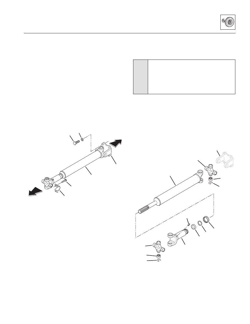
Drive Shaft Disassembly
IMPORTANT: To help ensure optimum performance, the
drive shaft assemblies are specially balanced as a unit at
the factory. When servicing any flange yoke, slip yoke, or
drive shaft tube, order a complete assembly if compo-
nents are bent or damaged. Refer to the appropriate
parts manual for ordering information.
a. Transmission-to-Axle Drive Shafts
1. Use an approved, non-flammable cleaning fluid to
thoroughly clean the drive shaft assembly with a
brush. Wipe dry before disassembling.
2. Place the drive shaft assembly in a bench vise.
3. Use a pair of pliers to pinch the ends of the snap
rings (Fig. 5-12, 1) securing the cross (2) and
bearing (3) assemblies to the yoke (4 or 5). Remove
the snaps rings from their grooves in the yoke.
Note: If the snap rings fail to readily snap out of their
grooves in the yokes, tap the end of the bearing cap
lightly to help relieve pressure against the snap rings.
Figure 5-12 Drive Shaft Construction
MA8900
2
1
6
5
4
3
To
Transmission
To
Engine
CAUTION:
Avoid using excess force
when clamping the drive shaft in a vise. Apply
only enough force to hold the drive shaft
securely. Excessive force can damage the
drive shaft, resulting in an unbalanced
condition.
MA8910
2
3
1
4
9
2
3
1
6
7
8
5
10