Service brake switch – SkyTrak 6042 Service Manual User Manual
Page 504
Electrical System
9.134
Model 6042 Legacy
Origin 7/02
9.15.17
Service Brake Switch
The service brake switch works in conjunction with the
Stabil-TRAK™ system. With the boom above 40° and the
service brake depressed, the Stabil-TRAK™ system will
engage. There are other function combinations which will
engage the Stabil-TRAK™ system, for more information,
refer to Section 10.2, “Stabil-TRAK™ Description.” If the
Service Brake Switch is suspect in the proper operation
of the Stabil-TRAK™ system, refer to Section 10.6, “Sta-
bil-TRAK™ System Test.”
a. Service Brake Switch Removal
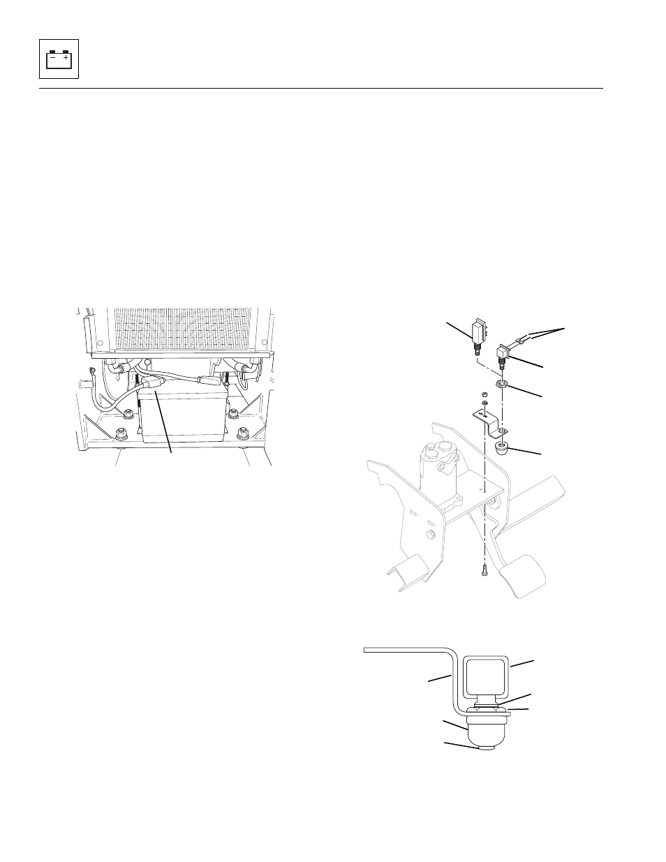
1. Disconnect the negative (–) battery cable at the
negative battery terminal (Fig. 9-134, 1).
Figure 9-134 Battery Cable Connections
2. Label and disconnect the cab harness electrical
connectors (Fig. 9-135, 1) from the service brake
switch.
Note: If roadlight option is installed the brake switch
(Fig. 9 -135, 2) will be longer and there will be more elec-
trical connections made.
3. Loosen locknut (Fig. 9 -135, 3) and remove switch
dust cover (4). Remove switch body (5).
b. Service Brake Switch Installation
1. Ensure that there is only one thread (Fig. 9-136, 1)
showing above the locknut (2) on the shaft of the
switch body (3).
2. Insert switch body (Fig. 9-136, 3) through the top of
the service brake switch bracket (4).
3. Thread the switch dust cover (Fig. 9-136, 5) onto the
switch body (3) until finger tight against the service
brake switch bracket (4).
4. Use a wrench and fully tighten the locknut
(Fig. 9-136, 2) against the service brake switch
bracket (4). There should now be approximately two
or three threads showing above the locknut.
5. Thread the bottom lip (Fig. 9-136, 6) of the switch
plunger through the hole in the bottom of the dust
cover (5).
6. Connect the cab harness electrical connectors
(Fig. 9-135, 1) to the service brake switch (5)
connectors.
7. Connect the negative (–) battery cable at the
negative battery terminal (Fig. 9 -134, 1).
8. Adjust the brake switch. (Refer to Section 9.15.17, c.
“Service Brake Switch Adjustment.”)
Figure 9-135 Service Brake Switch Installation
Figure 9-136 Service Brake Locknut and Dust Cap
Installation.
MA8410
1
MH3521
2
1
4
5
3
1
2
3
MA10,0710
4
5
6