Fig. 3-54 – SkyTrak 6042 Service Manual User Manual
Page 69
3.23
Model 6042 Legacy
Origin 7/02
Boom
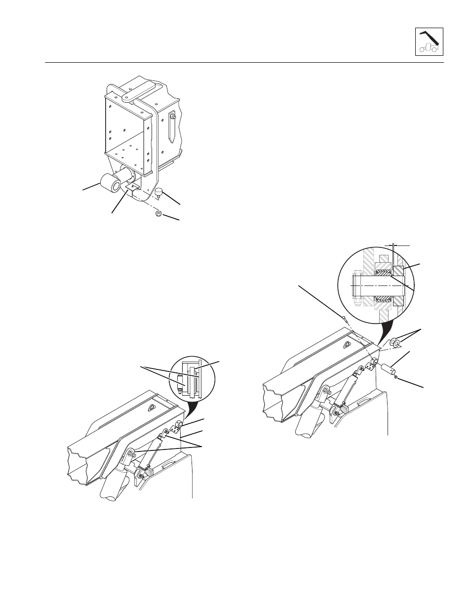
Figure 3-54 Rubber Bumper
Note: Use a hoist capable of lifting 5,000 lbs (2268 kg)
and two slings to install the outer boom.
10. Using a capable hoist and slings, lift the outer boom
assembly and position the boom on the frame. Align
the mounting plates (Fig. 3-55, 1) on the frame between
the mounting hubs (2) on each side of the boom
assembly. Be sure the lift/lower and slave cylinder
mounts on the boom go between the cylinder rod
ends (3). Lower the boom assembly until the holes in
the boom assembly and the mounting plates align.
Figure 3-55 Outer Boom Installation
11. On the end of the boom pivot pin (Fig. 3-56, 1),
closest to the capscrew hole, mark the capscrew
mounting hole location. Coat the entire pin with
anti-seize compound.
12. Insert the pivot pin (Fig. 3-56, 1) from the outside of
the boom assembly, making sure the marks for the
capscrew mounting hole stay in line with the
capscrew mounting holes in the boom mounting hub.
If necessary, use a rawhide hammer to install the
pivot pin.
13. Shim the boom as required using the shims
(Fig. 3 -56, 2), saved, to maintain a .10" (2,5 mm)
maximum gap (3) between the boom mounting
hub (4) and the self aligning bearing (5) in the frame.
If an additional shim is required to maintain the
maximum gap, insert the extra shim on the right side
of the boom.
Figure 3- 56 Boom Pivot Pin and Shims
14. After the pivot pin and shims are in place, use a
tapered punch to align the capscrew hole in the pin
with the mounting holes in the hub. Insert the
capscrew (Fig. 3-56, 6), saved, through the hub and
the pin. Secure the capscrew in place with a new
5/8-11 elastic locknut (7). Tighten the elastic locknut
securely.
MA10,0530
1
3
2
4
MA9730
1
3
1
2
2
MA9740
1
7
2
3
4
6
5