Warning – SkyTrak 6042 Service Manual User Manual
Page 301
8.69
Model 6042 Legacy
Origin 7/02
Hydraulic System
b. Unloader Valve Disassembly, Inspection and
Assembly
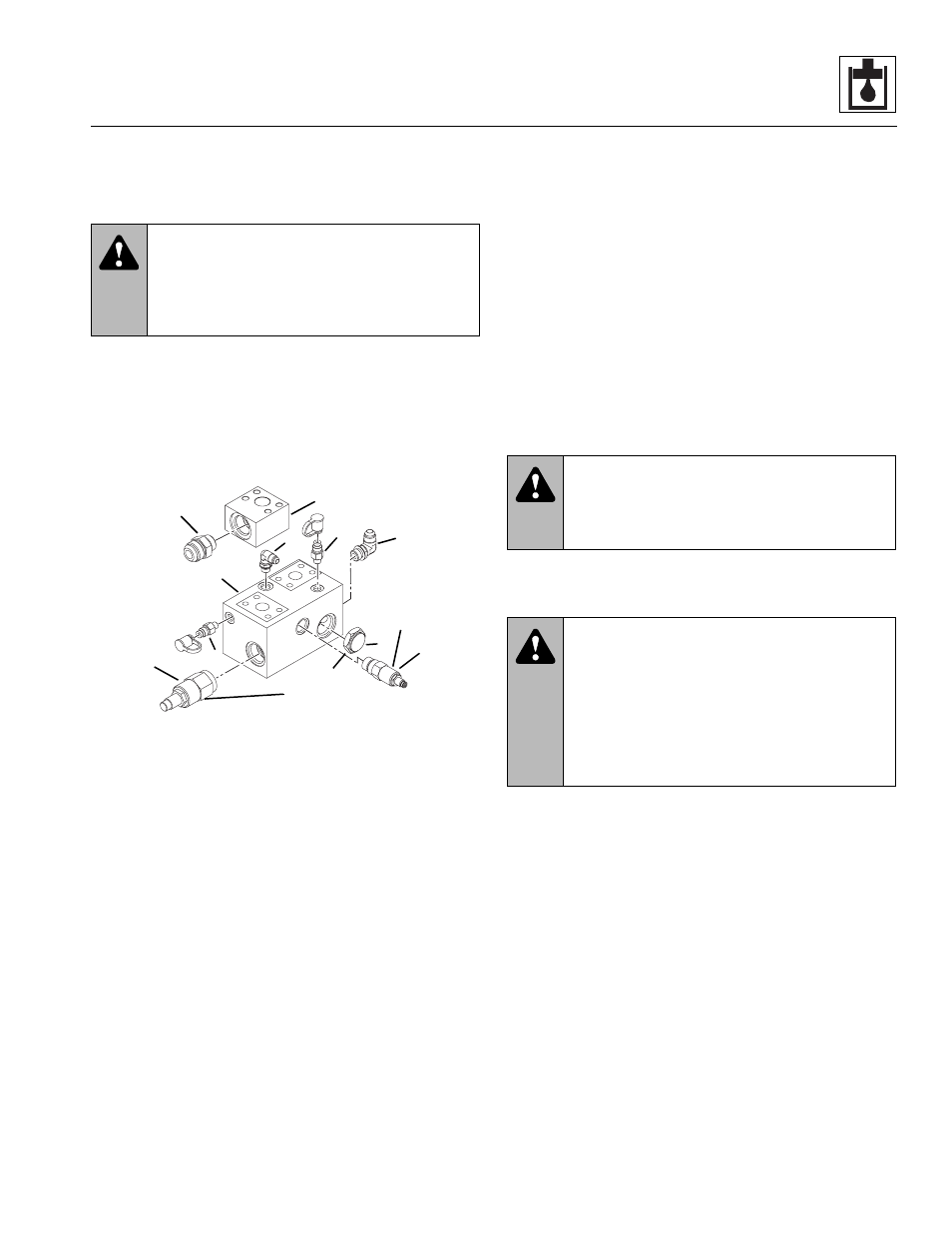
1. Safely secure the unloader valve (Fig. 8-36, 1) in a
bench vise or by other suitable means.
2. Slowly remove the check valve (Fig. 8 -36, 2).
3. Remove the relief valve (Fig. 8-36, 3) and remove
the differential pressure sense valve (4).
4. Remove the diagnostic test nipples (Fig. 8 -36, 5)
and remaining fittings (6). Remove the fitting (8) from
the manifold (7).
Figure 8-36 Unloader Valve Components
5. Clean metal parts with an approved solvent such as
triclorethylene and blow dry.
6. Inspect all sealing surfaces. They must be clean,
smooth and free of damage, and have no indication
of wear. Replace parts if damaged or worn.
Note: ALWAYS replace seals, o-rings, gaskets, etc.,
with new parts to help ensure proper sealing and operation.
Lubricate seals and o-rings with clean hydraulic oil.
7. Install the check valve (Fig. 8-36, 2) and torque to
80-90 lb-ft (108-122 Nm).
8. Install the relief valve assembly (Fig. 8-36, 3) and
torque to 35-40 lb-ft (47-54 Nm).
9. Install the differential pressure sense valve assembly
(Fig. 8-36, 4) and torque to 80-90 lb-ft (108-122 Nm).
10. Install diagnostic nipples (Fig. 8-36, 5) and fittings (6).
Install the fitting (8) on the manifold (7).
c. Unloader Valve Installation
1. Secure the unloader valve (Fig. 8-35, 1) to the
vehicle frame with the three hex-head capscrews (7),
the three lockwashers (8) and the three washers (9).
Torque the capscrews to 31 lb-ft (42 Nm). Secure the
check valve manifold (10) to the unloader valve with
the flange connection.
Note: ALWAYS replace seals, o-rings, gaskets, etc.,
with new parts to help ensure proper sealing and operation.
Lubricate seals and o-rings with clean hydraulic oil.
2. Connect the hydraulic lines to their appropriate ports
on the unloader valve or check valve manifold.
3. Check the routing of all hoses, wiring and tubing for
sharp bends or interference with any rotating
members. All tube and hose clamps must be tight.
4. Start the engine and run at approximately one-third
to one-half throttle for approximately one minute without
moving the vehicle or operating any hydraulic functions.
5. Inspect for leaks and check all fluid levels. The
hydraulic reservoir oil level must be to the middle of
the sight gauge.
Note: Check for leaks and tighten fittings or repair as
required before continuing. Wipe up any hydraulic fluid
spillage in, on, near and around the vehicle, work area and
tools.
d. Unloader Valve Pressure Check Test
1. Monitor the valve pressure at the VG test port
(Fig. 8 -36, 7) on the unloader valve. It should be at
250-300 psi (17-21 bar) within moments after
starting the engine. Adjust the differential pressure
sense valve as required.
2. Check the pressure at the VG test port (Fig. 8-36, 7)
on the unloader valve while performing the boom lower
function. It should be 3,000 psi (207 bar). Adjust the
relief valve as required.
WARNING:
Significant pressure may be
trapped inside the valve. Exercise caution
when removing a valve. Escaping hydraulic
fluid under pressure can penetrate the skin,
causing death or serious injury.
LSG
P
T
VG
LS
MA7150
1
2
3
4
Torque to
80-90 lb-ft
(108-122 Nm)
Torque to
35-40 lb-ft
(47-54 Nm)
6
5
5
7
8
6
WARNING:
Avoid prolonged engine
operation in closed areas with inadequate
ventilation. Failure to properly ventilate exhaust
fumes can result in death or serious injury.
WARNING:
Hydraulic oil leaking under
pressure can penetrate the skin and cause
severe personal injury. DO NOT use your hand
or any part of your body to check for hydraulic
leaks. When checking for hydraulic leaks, wear
safety glasses and gloves to help provide
protection from spraying hydraulic oil. Use a
piece of cardboard or paper to search for leaks.