Fig. 4-23 – SkyTrak 6042 Service Manual User Manual
Page 135
4.15
Model 6042 Legacy
Origin 7/02
Cab and Covers
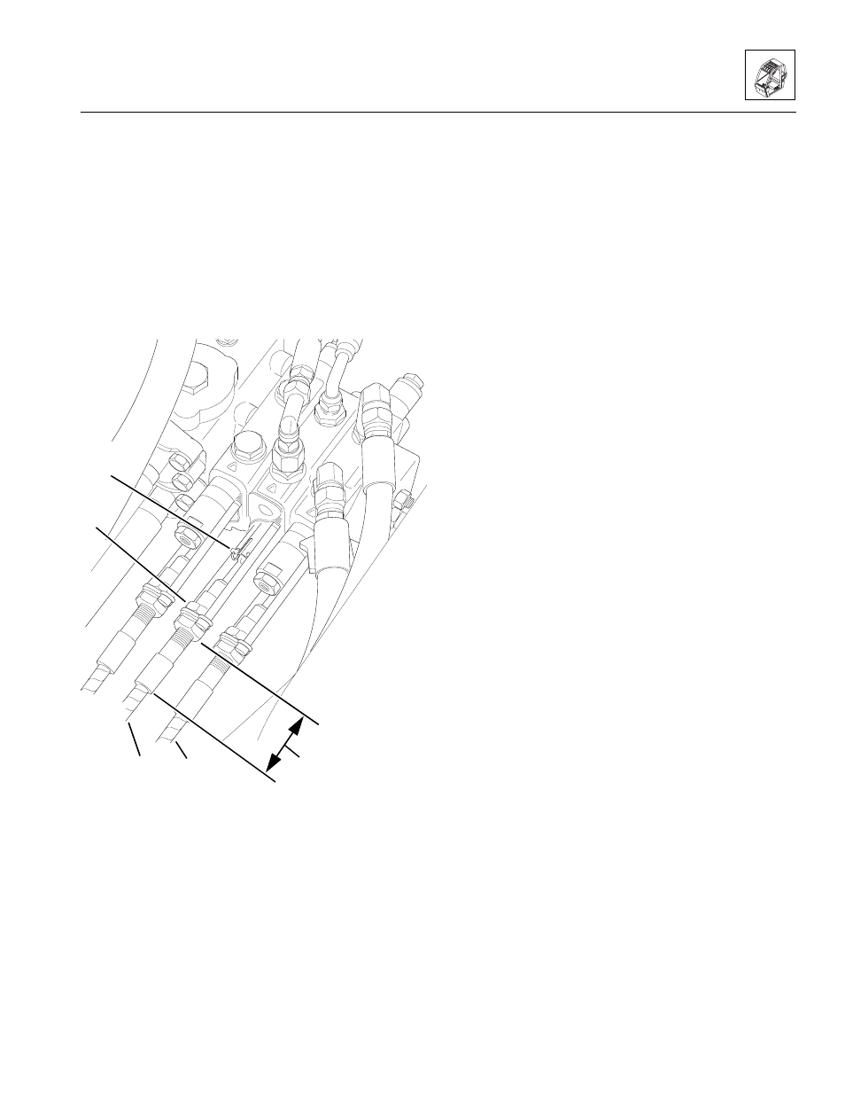
9. Disconnect the frame sway control cable (Fig. 4-23, 2):
a. Remove the spring pin (Fig. 4-23, 3) and anchor
pin. Save the spring pin and anchor pin for
installation.
b. Loosen and remove the inner jam nut (Fig. 4-23, 4),
and remove the frame sway control cable from
the bracket. Save the jam nut for installation.
c. Route the cable through the opening at the
bottom of the frame.
10. Repeat Step 9 to remove the attachment tilt control
cable (Fig. 4-23, 5).
Figure 4-23 Disconnect the Frame Sway and
Attachment Tilt Control Cables
b. Control Cable Installation
1. Route the control cables through the opening at the
bottom of the frame.
2. Connect the frame sway control cable to the main
control valve assembly:
a. Install the cable in the bracket, and slide the
inner jam nut (Fig. 4 -23, 4) over the end of the
frame sway control cable (2). DO NOT tighten the
jam nuts at this time.
b. Connect the end of the cable to the shaft from
the control valve. Secure with an anchor pin and
spring pin (Fig. 4-23, 3).
c. Adjust the jam nuts until the distance (Fig. 4-23, 1)
from the outer jam to the end of the ferrule is the
same as recorded during removal. Tighten the
jam nuts.
3. Repeat Step 2 to install the attachment tilt control
cable (Fig. 4-23, 5).
1
MA8490
2
3
4
5