SkyTrak 6042 Service Manual User Manual
Page 296
Hydraulic System
8.64
Model 6042 Legacy
Origin 7/02
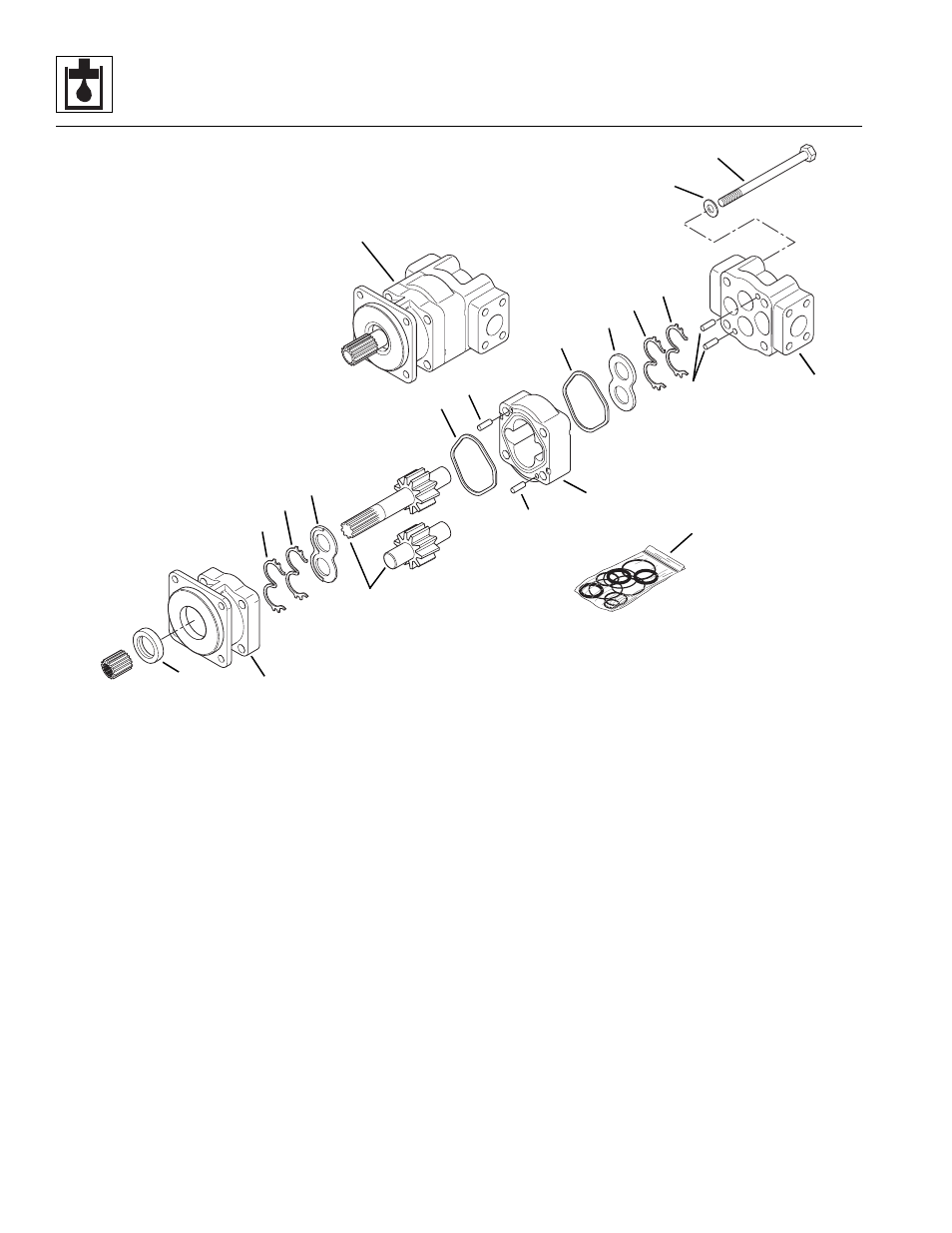
Figure 8-31 Hydraulic System Pump
d. Pump Disassembly
1. Secure the pump (Fig. 8-31, 1) with the pump drive
shaft pointing down in a suitable holding device or
bench vise if possible. Scribe or otherwise make a
mark across the two pump housings (2 and 3) and
the gear housing (4), perpendicular to the parting
lines for easy identification and proper alignment
during assembly later.
2. Remove the four capscrews (Fig. 8 -31, 5) and
washers (6) that secure the two pump housings
(2 and 3) together.
3. Carefully separate the pump housings
(Fig. 8-31, 2 and 3) from the gear housing (4). If it
becomes necessary to pry the components apart,
proceed carefully and DO NOT damage the
machined surfaces or internal components. Dowel
pins (7) will remain installed in most cases; DO NOT
remove dowel pins unless they are damaged.
4. Remove the square “R” seals (Fig. 8-31, 8), channel
seals (9), back-up seals (10) and thrust plates (11).
5. Carefully remove the drive and driven gear set
(Fig. 8-31, 12). To help avoid damaging the gears,
DO NOT tap the gear teeth together or against other
hardened surfaces. Keep the matched gears
together as a set.
6. Carefully clamp the Shaft End Cover (SEC) housing
(Fig. 8-31, 2) in a vise with the mounting face down.
Remove the lip seal (13) with a suitable seal removal
tool.
e. Pump Cleaning
Clean all pump components with a suitable cleaner such
as trichlorethylene.
MT1410
1
2
3
4
5
6
7
8
9
10
11
12
13
14
7
7
11
9
10
8