Electrical system components, Warning devices, 12 electrical system components – SkyTrak 6042 Service Manual User Manual
Page 459
9.89
Model 6042 Legacy
Origin 7/02
Electrical System
9.12
ELECTRICAL SYSTEM
COMPONENTS
Electrical components include warning devices such as
the indicators in the operator’s instrument cluster, horn,
back-up alarm, and other components such as the
various solenoids and all accessories.
Examine the appropriate wiring diagrams and schematics
earlier in this section, to help understand the wiring
circuits involved.
9.12.1
Warning Devices
Vehicle warning devices include the horn, instrument
cluster warning lights and the back-up alarm.
a. Horn
The horn (Fig. 9 -50, 1) is mounted on the vehicle frame.
Figure 9-50 Horn Location as Viewed from Below Vehicle
The horn sounds when the momentary-contact horn
button on the center of the steering wheel is pressed.
Removal of the horn button is discussed in Section 4.3.2,
a. “Steering Wheel Removal” of this manual.
The horn sound is produced by a solenoid-actuated
diaphragm in the horn that develops a resonating air
column in the horn trumpet, which is shaped to project the
sound. If the horn does not sound when the horn button
is pressed, check that the fuse is not blown.
Check for corrosion on the horn mounting that may be
preventing a solid ground, and check for a loose horn
wire. Test the horn switch for continuity when the horn
button is pressed.
If the problem is still not located, unplug the horn
connector (Fig. 9-50, 2), remove the nut attaching the
horn to frame (not shown) and test the horn using short,
heavy-gauge wires connected to a fused or otherwise
protected 6-amp minimum output, 12-volt DC power
supply. If the horn does not sound, replace the horn.
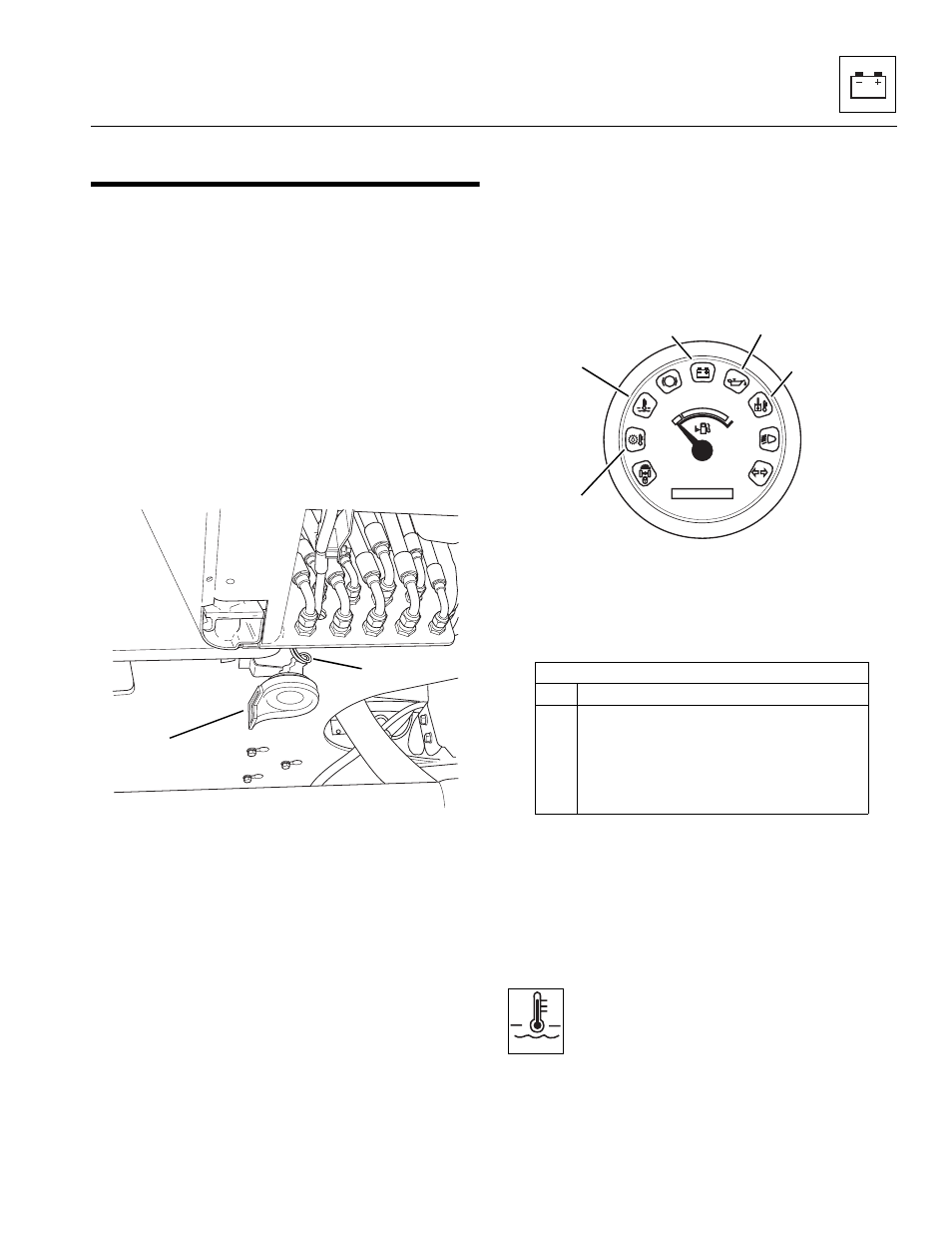
b. Warning Indicator Lights
(In Operator’s Instrument Cluster)
Figure 9-51 Typical Operator’s Instrument Cluster
Warning Indicators
There are five subdued or “hidden” warning indicator
lights present in the instrument cluster. These warning in-
dicators illuminate during critical circumstances.
IMPORTANT: All five
warning indicator lights demand
immediate attention and vehicle service. In many cases,
the vehicle should be shut down as soon as practical to
help prevent serious mechanical failure. Appropriate
service procedures for each circuit, as applicable,
appear elsewhere in this section of the manual.
c. Engine Coolant Temperature Warning Indicator
This indicator (Fig. 9-51, 1) is illuminated when
the engine coolant temperature is above 210° F
(99° C). An audible alarm will sound, and the
engine must be shut down as soon as practical
to help avoid engine damage. For additional information
refer to Section 9.9.2, “Engine Coolant Temperature
Warning Indicator Troubleshooting.”
MA7960
1
2
Item
Description
1
Engine Coolant Temperature Indicator
2
Transmission Temperature Indicator
3
Hydraulic Oil Temperature Indicator
4
Alternator Charging Indicator
5
Engine Oil Pressure Indicator
0000 00
P
OH1810
OH25202