SkyTrak 6042 Service Manual User Manual
Page 150
Cab and Covers
4.30
Model 6042 Legacy
Origin 7/02
6. Route the throttle cable through the hole in the
bulkhead plate (Fig. 4-48, 1) under the cab.
7. Connect the throttle cable to the throttle pedal.
Follow steps 4 through 6 at Section 4.3.5, b. “Throttle
Pedal Installation.”
8. Install the auxiliary hydraulics joystick assembly.
(Refer to Section 4.3.8, b. “Auxiliary Hydraulics
Joystick Installation.”)
Note: ALWAYS use new o-rings when servicing the
vehicle.
9. Install new o-rings into the fittings. Lubricate the o-rings
with clean hydraulic oil.
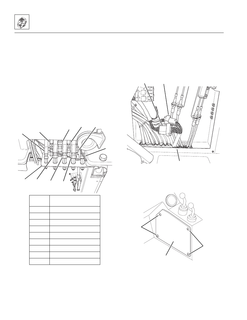
10. Working under the cab, connect the hydraulic hoses
(Fig. 4-48, 2 through 10) at the cab fittings on the
bulkhead plate (1).
Figure 4-48 Connect Hydraulic Hoses
11. Route the control cables through the opening at the
bottom of the cab.
12. Connect the control cables to the joystick
assemblies. Refer to Section 4.3.6, b. “Joystick
Assembly Installation.”
13. Route the wiring harness connectors through the
opening (Fig. 4 -49, 1) at the bottom of the cab.
14. Connect the two cab-to-wiring harness connectors
(Fig. 4-49, 2 and 3).
Figure 4-49 Connect the Wiring Connectors
15. Install the console panel (Fig. 4-50, 1), and secure
using four button-head screws (2).
Figure 4- 50 Install the Console Panel
16. Install the lower (Fig. 4-51, 1) and upper (2)
transmission covers; secure using six hex-head
capscrews, six lockwashers and six flat washers (3).
MA8501
3
2
4
5
7
8
9
10
1
Hose
Number
Function
2
Right Rear Service Brake
3
Left Rear Service
4
Steering Orbital “T” Port
5
“LS” Shuttle Out
6
Brake Valve “LS” Port
7
Steering Orbital “L” Port
8
Steering Orbital “R” Port
9
Brake Valve “T” Port
10
Steering Orbital “P” Port
6
MA8470
3
1
2
OH2430
2
1
~
2