Transmission inspection and internal repair, Transmission installation, Warning – SkyTrak 6042 Service Manual User Manual
Page 188
Transmission: ZF 4 WG-98 TC
6.10
Model 6042 Legacy
Origin 7/02
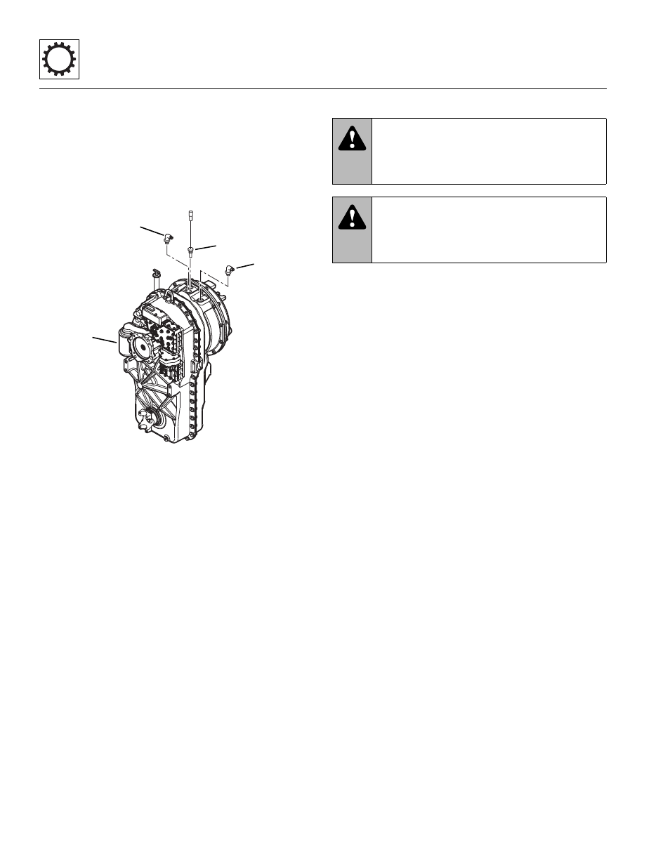
28. Remove any external transmission components as
required, including the transmission temperature
switch (Fig. 6-10, 1), and inlet (2) and outlet (3)
cooler hose fittings. Cover all transmission openings.
29. Remove the transmission oil filter (Fig. 6-10, 4) and
dispose of it properly. Clean the filter mounting
surface. Cover or cap the oil filter mount.
Figure 6-10 Transmission External Components
The transmission is now ready for inspection and/or
further service. Refer to the ZF 4 WG-98 TC
Transmission Repair Manual, OmniQuip P/N 8990455
(ZF P/N 5871 135 002) for information on transmission
diagnosis, and internal component repair or replacement.
6.7.2
Transmission Inspection and Internal
Repair
Refer to the ZF 4 WG-98 TC Transmission Repair
Manual, OmniQuip P/N 8990455 (ZF P/N 5871 135 002)
for information on internal component repair or
replacement. Refer to the ZF 4 WG-98 TC Transmission
Technical Data Manual and Maintenance Manual,
OmniQuip P/N 8990449 (ZF P/N 5872 134 002) for
information on transmission diagnosis and internal
schematics.
If replacing the entire transmission, transfer the
transmission temperature switch to the replacement
transmission. The gear shift solenoids are included with a
new transmission.
6.7.3
Transmission Installation
1. Install two rubber mounts (Fig. 6-11, 1) and the rear
transmission mount (2) in the vehicle frame. Secure
the mount with two hex-head capscrews (3), two
rebound washers (4) and two locknuts (5).
2. Use a hoist or overhead crane and sling attached to
the lifting eye (Fig. 6 -11, 6) at the top of the
transmission. Raise and position the transmission
within the chassis.
3. Attach the transmission to the rear mounting bracket
(Fig. 6-11, 2) with four hex-head capscrews (7) and
four lockwashers (8). Torque the capscrews to
148 lb-ft (200 Nm).
4. Install the two front rubber mounts (Fig. 6-11, 9) and
the front transmission mounting bracket (10). Secure
the mounting bracket to the transmission with four
hex-head capscrews (11) and four lockwashers (12).
Torque the capscrews to 148 lb-ft (200 Nm).
5. Attach the front mounting bracket (Fig. 6-11, 10) to
the frame with two hex-head capscrews (13), two
hex locknuts (14) and two rebound washers (15).
6. Remove the hoist or overhead crane and sling.
MA8970
1
3
2
4
WARNING:
Risk of severe personal
injury. NEVER lift a transmission alone; enlist
the help of at least one assistant or use a
suitable hoist or overhead crane and sling.
WARNING:
The transmission must be
properly installed using fasteners of the correct
size and grade, and torqued to their specified
values.