SkyTrak 6042 Service Manual User Manual
Page 305
8.73
Model 6042 Legacy
Origin 7/02
Hydraulic System
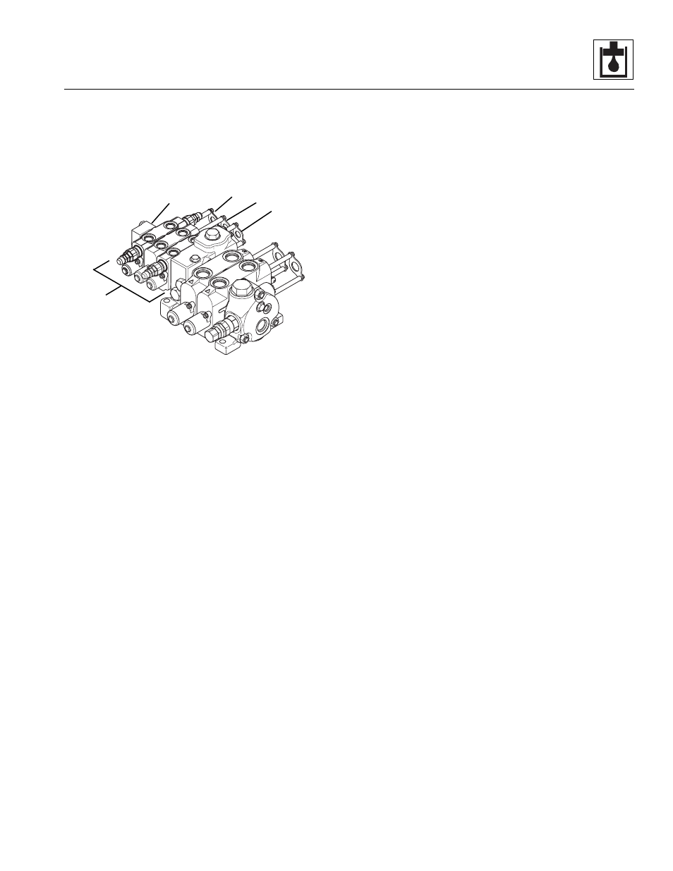
b. Main Control Valve Disassembly
This section covers disassembly of one half (Fig. 8 -41, 1)
of the main control valve, including the auxiliary
hydraulics (2), frame sway (3), attachment tilt (4) and load
sense outlet (5) sections of the main control valve.
Figure 8-41 Main Control Valve
1. To disassemble the auxiliary, frame sway,
attachment tilt and load sense outlet sections of the
main control valve (Fig. 8-40, 1), remove the
nuts (2 and 66) from the end of the tie
rods (3 and 67). Pull the tie rods out through the
sections.
2. Disassemble each section assembly as required.
Some sections include a pre-adjusted relief valve that
regulates pressure in a specific circuit.
IMPORTANT: DO NOT adjust any of the relief valve
assemblies! Tampering with a relief valve will irrevocably
alter pressure in the affected circuit, requiring re-calibration
or a new relief valve.
Disassemble the Load Sense Outlet Section
1. Carefully separate the load sense outlet section
(Fig. 8-40, 4) from the attachment tilt section (5).
Avoid dislodging or losing the spring (6) and
poppet (7) in the attachment tilt section.
2. Remove the o-ring (Fig. 8-40, 8) from between the
two sections.
3. Remove the shut-off plug (Fig. 8 -40, 9) and
o-ring (10) from the load sense outlet section (4).
Disassemble the Attachment Tilt Section
1. Carefully separate the attachment tilt section
(Fig. 8-40, 5) from the frame sway section (11). Avoid
dislodging or losing the shuttle (12), spring (13) and
poppet (14) in the frame sway section.
2. Remove the o-ring (Fig. 8-40, 15) from between the
two sections.
3. Remove the spring (Fig. 8 -40, 6) and poppet (7)
from the attachment tilt section (5).
4. Remove both socket head capscrews (Fig. 8-40, 24)
securing the cable retainer assembly (22) to the
attachment tilt section (5).
5. Remove the retainer (Fig. 8-40, 25), both
sleeves (26), another retainer (25), wiper (27) and
o-ring (28) from the cable retainer assembly (22).
6. Remove both socket head capscrews (Fig. 8-40, 29)
securing the end mechanism (23) to the attachment
tilt section (5).
7. Remove the spool cap (Fig. 8-40, 30), retainer (25),
spool end (31), o-ring (36), spring seat (32),
spring (33), another spring seat (32), wiper (34) and
o-ring (35) from the end mechanism (23).
Disassemble the Relief Valve
The relief valve assemblies (Fig. 8-40, 43) are part of the
attachment tilt section. The valves are preset at
3,250 ±50 psi (224 ±3,5 bar).
Note: If the vehicle includes auxiliary hydraulics, there
will be relief valve assemblies (Fig. 8-40, 16) on the
auxiliary hydraulics section also. These valves are
preset at 3,250 ±50 psi (224 ±3,5 bar).
1. Remove the relief valve (Fig. 8-40, 43) and
o-ring (44) from the applicable section assembly.
2. Grip the relief valve body (Fig. 8-40, 45) with a
suitable tool and use another tool to remove the
nut (46), revealing an o-ring (47) and the adjustment
screw (48).
3. Carefully remove the plug (Fig. 8-40, 49),
spring (50) and pilot poppet (51).
4. Remove the large o-ring (Fig. 8-40, 52), back-up
ring (53), small o-ring (54), large spring (55), small
spring (56), piston (57), o-ring (58), back-up ring (59)
and relief valve poppets (60 and 61).
MA10,0200
1
2
3
4
5