Brake pedal and valve – SkyTrak 6042 Service Manual User Manual
Page 130
Cab and Covers
4.10
Model 6042 Legacy
Origin 7/02
4.3.4
Brake Pedal and Valve
a. Brake Valve Removal
Refer to Section 8.12.4, a. “Service Brake Valve
Removal” for removal information.
b. Brake Valve Installation
Refer to Section 8.12.4, b. “Service Brake Valve
Installation” for installation information.
c. Service Brake Pedal Removal
1. Park the vehicle on a firm, level surface. Level the
vehicle, ground the attachment, place the travel
select lever in the (N) NEUTRAL position, place the
neutral lock lever in the (N) NEUTRAL LOCK
position, engage the parking brake switch and shut
the engine OFF.
2. Place an Accident Prevention Tag on both the
ignition key switch and steering wheel, stating that
the vehicle should not be operated. (Refer to Section
1.5, “Accident Prevention Tag Usage.”)
3. Unlock and open the rear door. Allow the engine and
hydraulic fluid to cool.
4. Disconnect the battery negative (-) cable at the
battery negative (-) terminal.
5. Remove the four button-head screws securing the
lower dash panel (Fig. 4-14, 1) to the cab. Remove
the lower dash panel.
Figure 4-14 Remove the Lower Dash Panel
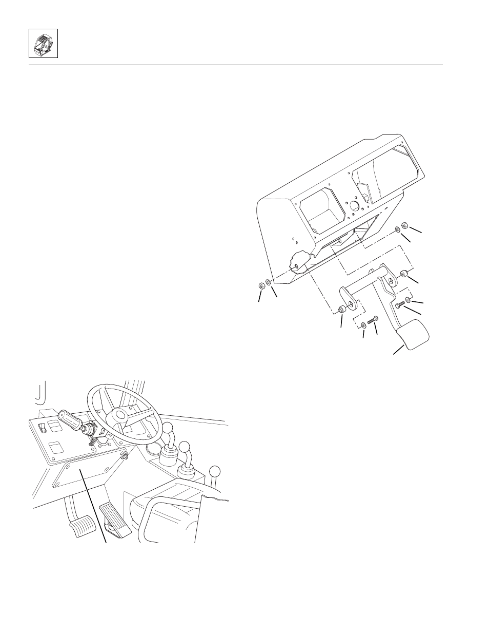
6. Remove the two hex-head capscrews (Fig. 4-15, 1),
four flat washers (2), two pivots (3), and two hex nuts
(4) securing the service brake pedal (5) to the cab.
7. Remove the service brake pedal (Fig. 4-15, 5) from
the cab.
Figure 4-15 Service Brake Pedal Mounting Arrangement
d. Service Brake Pedal Installation
1. Position the service brake pedal (Fig. 4 -15, 5) in its
mounting location within the cab.
2. Insert two brake pedal pivots (Fig. 4-15, 3) into their
mounting locations on the service brake pedal.
3. Insert one flat washer (Fig. 4-15, 2) onto a hex-head
capscrew (1). Work the capscrew through one side
of the brake pedal-to-cab mounting support. Secure
with a flat washer (2) and a hex nut (4). Repeat for
the other side.
4. Adjust the brake switch as needed. (Refer to Section
9.15.17, c. “Service Brake Switch Adjustment.”)
5. Install and secure the lower dash cover (Fig. 4-14, 1)
with four button-head screws.
6. Connect the battery negative (-) cable.
MA8560
1
~
MA8690
1
2
5
4
3
1
2
2
2
3
4