Electrical components – SkyTrak 6042 Service Manual User Manual
Page 138
Cab and Covers
4.18
Model 6042 Legacy
Origin 7/02
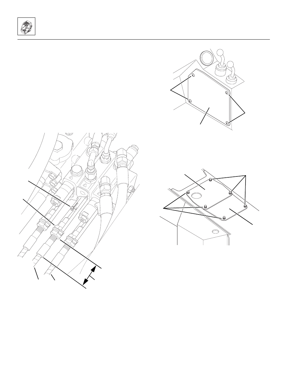
3. Connect the auxiliary hydraulics control cable to the
main control valve:
a. Slide the inner jam nut (Fig. 4-29, 1) over the
end of the auxiliary hydraulics control cable (2),
and install the cable in the bracket with one nut
on either side of the bracket. DO NOT tighten the
jam nuts at this time.
b. Connect the end of the cable to the shaft from
the control valve. Secure with an anchor pin and
spring pin (Fig. 4-29, 3).
c. Adjust the jam nuts until the distance (Fig. 4-29, 4)
from the outer jam nut to the end of the ferrule is
the same as recorded during removal. Tighten
the jam nuts.
Figure 4-29 Connect the Auxiliary Hydraulics Control
Cable to the Main Control Valve
4. Install the joystick access panel (Fig. 4 -30, 1) and
secure using four button-head screws (2).
Figure 4- 30 Install the Joystick Access Panel
5. Install the lower (Fig. 4-31, 1) and upper (2)
transmission covers; secure using six hex-head
capscrews, six lockwashers and six flat washers (3).
Figure 4- 31 Install the Upper and Lower
Transmission Covers
4.3.9
Electrical Components
a. Fuse Panel/Cab Harness
Refer to Section 9.1.1, “General Overview (Cab
Harness).”
4
MA8490
2
3
1
5
OH2430
2
1
~
2
MA8620
3
~
~
2
1
3