Steering wheel, column and shifter – SkyTrak 6042 Service Manual User Manual
Page 125
4.5
Model 6042 Legacy
Origin 7/02
Cab and Covers
4.3.2
Steering Wheel, Column and Shifter
The steering wheel and transmission travel and gear
select lever are mounted on the steering column.
a. Steering Wheel Removal
1. Park the vehicle on a firm, level surface. Level the
vehicle, ground the attachment, place the travel
select lever in the (N) NEUTRAL position, place the
neutral lock lever in the (N) NEUTRAL LOCK
position, engage the parking brake switch and shut
the engine OFF.
2. Place an Accident Prevention Tag on both the
ignition key switch and steering wheel, stating that
the vehicle should not be operated. (Refer to Section
1.5, “Accident Prevention Tag Usage.”)
3. Disconnect the battery negative (-) cable at the
battery negative (-) terminal.
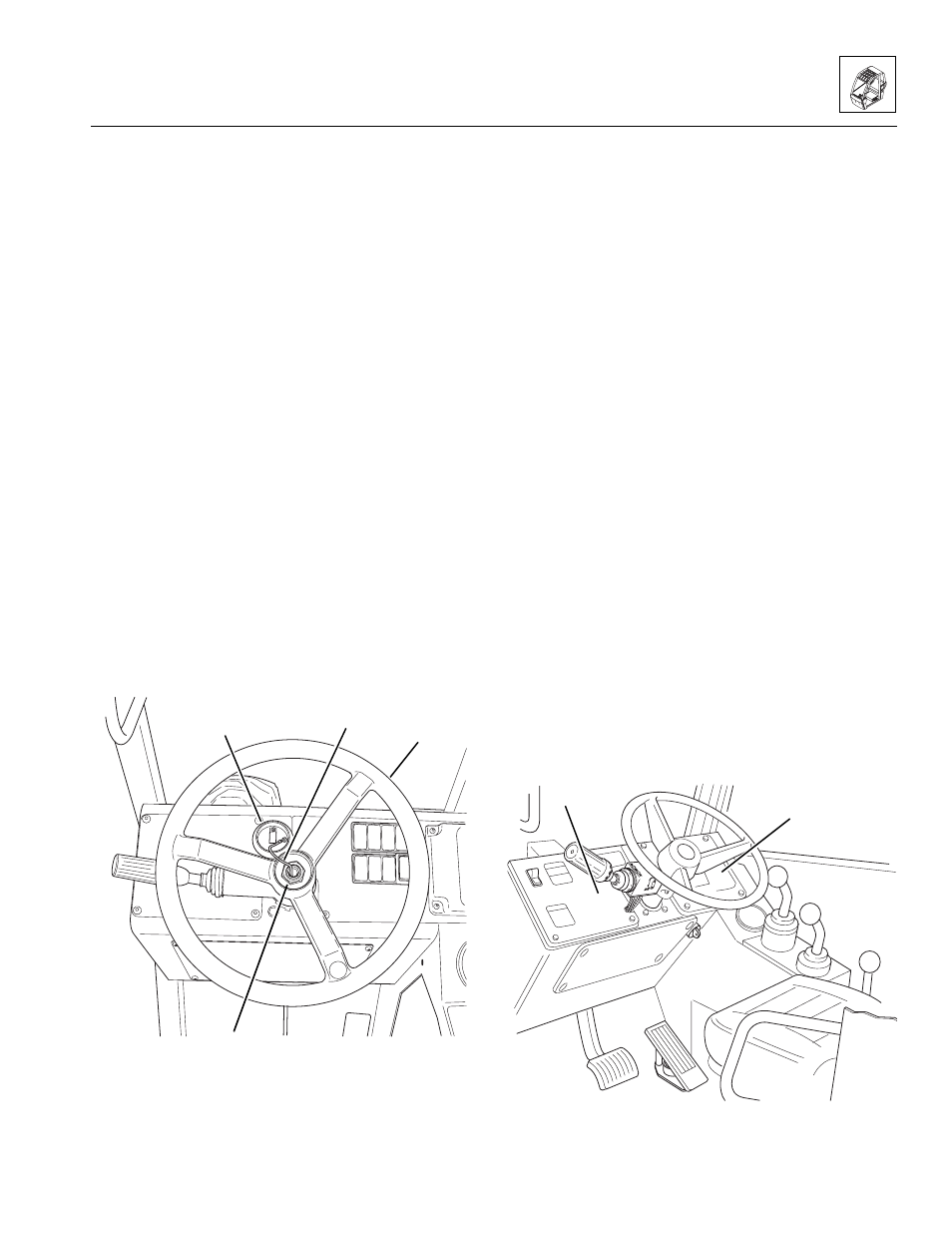
4. Carefully pry the horn button (Fig. 4-4, 1) out of its
recess in the steering wheel. Disconnect the horn
switch lead (2).
5. Mark the steering wheel and shaft to ensure proper
installation. Remove the M18-1,5 thin nut (Fig. 4-4, 3)
securing the steering wheel (4) to the splined
steering column shaft.
6. Use a steering wheel puller to remove the steering
wheel (Fig. 4-4, 4) from the splined shaft.
Figure 4-4 Remove Steering Wheel
b. Steering Wheel Installation
1. Install the steering wheel (Fig. 4 -4, 4) onto the
splined steering column shaft.
2. Secure the steering wheel with a M18-1,5 thin nut
(Fig. 4 -4, 3). Torque the nut to 50 lb-ft (68 Nm).
3. Connect the horn switch lead (Fig. 4-4, 2), then press
the horn button (1) into the recess in the steering wheel.
4. Connect the battery negative (-) cable.
c. Transmission Travel and Gear Select Lever
Removal
1. Park the vehicle on a firm, level surface. Level the
vehicle, ground the attachment, place the travel
select lever in the (N) NEUTRAL position, place the
neutral lock lever in the (N) NEUTRAL LOCK
position, engage the parking brake switch and shut
the engine OFF.
2. Place an Accident Prevention Tag on both the
ignition key switch and steering wheel, stating that
the vehicle should not be operated. (Refer to Section
1.5, “Accident Prevention Tag Usage.”)
3. Disconnect the battery negative (-) cable at the
battery negative (-) terminal.
4. Remove the four button-head screws securing the left
dash panel (Fig. 4-5, 1) to the cab; DO NOT
disconnect the wiring connectors. Set the dash
panel aside.
5. Remove the four button-head screws securing the right
dash panel (Fig. 4-5, 2) to the cab; DO NOT disconnect
the wiring connectors. Set the dash panel aside.
Figure 4-5 Remove Dash Panels
MA8660
1
2
4
3
MA8560
2
~
~
~
1