Warning – SkyTrak 6042 Service Manual User Manual
Page 349
8.117
Model 6042 Legacy
Origin 7/02
Hydraulic System
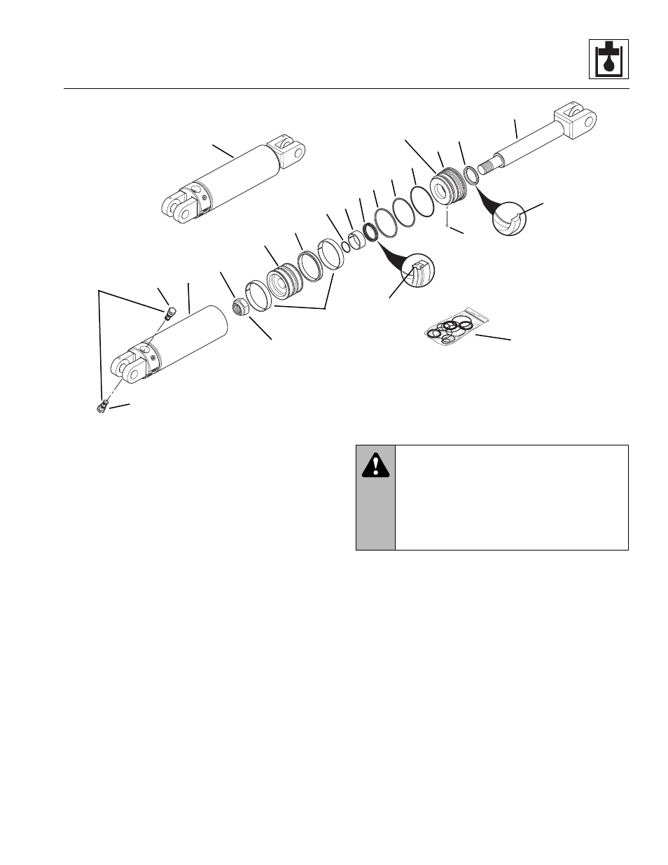
Figure 8-78 Frame Sway Cylinder Components
5. Disconnect and cap all hoses and fittings, etc.
6. Use a sling and hoist or other suitable lifting device
to support the cylinder. Remove the nuts,
capscrews, and cylinder mount pins securing the
cylinder to the frame and anchor plate.
7. Remove the cylinder from the vehicle. Wipe up any
hydraulic fluid spillage in, on, near and around the
vehicle.
b. Frame Sway Cylinder Disassembly
Note: An additional o-ring may be included at the base
of the cylinder rod. This additional o-ring may be discarded,
as it served only in a temporarily protective role.
1. Clean the frame sway cylinder (Fig. 8-78, 1) with a
suitable cleaner. Remove all dirt, debris and grease
from the cylinder.
IMPORTANT: Avoid using excess force when clamping
the cylinder in a vise. Apply only enough force to hold the
cylinder securely. Excessive force can damage the cylin-
der.
2. Secure the frame sway cylinder (Fig. 8-78, 1) in a
soft-jawed vise or other holding device, and place a
suitable container beneath the cylinder to catch
hydraulic fluid run-off.
3. Slowly remove the pilot-operated check valves
(Fig. 8 -78, 2) from the frame sway cylinder.
4. Remove the locking insert (Fig. 8-78, 3) from its hole
in the head gland threads. Pry or drill out the insert
as required. DO NOT damage the head gland threads.
A new locking insert will be required for reassembly.
IMPORTANT: Protect the finish on the rod at all times.
Damage to the rod can cause premature seal failure.
5. Use a pin spanner wrench to unthread the head
gland (Fig. 8-78, 4) from the tube (5). The head
gland is installed at a torque of 300-400 lb-ft
(407-542 Nm), so a considerable amount of force is
required to remove it. Carefully slide the head gland
down along the rod toward the eyelet end, away from
the cylinder tube.
MT1900
Apply Loctite #271 to
threads and torque to
1,100-1,250 lb-ft
(1.492-1.695 Nm)
7
8
14
13
12
17
16
9
11
1
4
15
5
2
2
10
3
18
6
Torque to
35-40 lb-ft
(47-54 Nm)
Torque to
300-400 lb-ft
(407-542 Nm)
19
20
WARNING:
Significant pressure may be
trapped inside the cylinder. Exercise caution
when removing a counterbalance valve or a
pilot-operated check valve from a cylinder.
Escaping hydraulic fluid under pressure can
penetrate the skin, causing death or serious
injury.