Section 9.15.9, “steer select valve.” t, Steer select valve – SkyTrak 6042 Service Manual User Manual
Page 493
9.123
Model 6042 Legacy
Origin 7/02
Electrical System
9.15.9
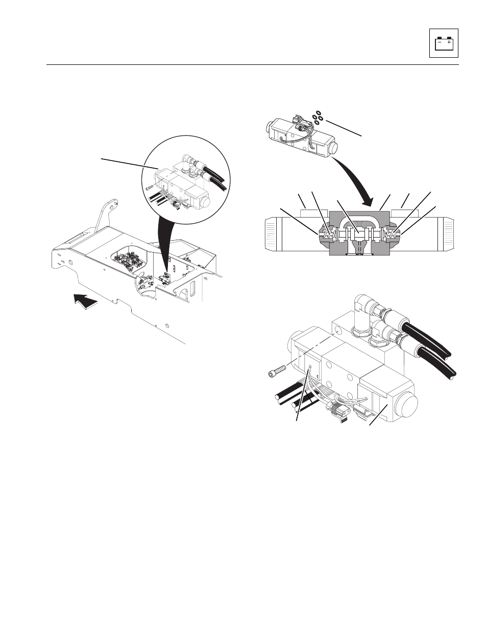
Steer Select Valve
The steer select valve (Fig. 9-112, 1), is secured to the
steer select manifold and frame with four capscrews and
o-rings (Fig. 9-113, 1) on the inside wall of the vehicle
frame.
Figure 9-112 Steer Select Valve Location
The steer select valve contains two solenoids that direct
hydraulic fluid through hoses and ultimately help operate
the steering. The valve is a direct dual-solenoid operated,
spool-type directional control valve. The steer select
valve controls the start, stop and direction of hydraulic
fluid flow to the steering cylinders mounted on each axle.
The valve consists of a housing (Fig. 9-113, 2), two
solenoids (3), a control spool (4) and two return
springs (5).
In the de-energized state, the spool (Fig. 9-113, 4) is held
by the return springs (5) in the center position. The spool
is shifted through the action of the two wet-pin type
solenoids (3).
The force of an acting solenoid works against the push
pin (Fig. 9-113, 6) on the end of the spool (4). The spool
is shifted from its normal position to the end position for
the selected flow. The selected flow pattern is covered in
Section 8, “Hydraulic System.”
When the solenoid is de-energized, the control spool
(Fig. 9 -113, 4) is returned to its normal (centered)
condition by the centering springs (5).
Figure 9- 113 Steer Select Valve Detail
Figure 9-114 Steer Select Valve
Check the steer select valve solenoids (Fig. 9-114,
1 and 2) for proper operation, and check the wiring for
continuity or shorts. When energized/de-energized, the
solenoid should move and/or an audible “click” should be
heard; check for the presence of voltage with a voltmeter.
Replace a defective or faulty steer select valve with a new
unit. (Refer to Section 9.7.15, “Front Steer Circuit and
Troubleshooting.”)
1
MA8320
MA8370
6
5
4
3
2
3
5
6
1
MA8310
6
3
2
1