To section, 7, “lift/lower cylinder.”), 7 lift/lower cylinder – SkyTrak 6042 Service Manual User Manual
Page 344: Warning
Hydraulic System
8.112
Model 6042 Legacy
Origin 7/02
8.13.7
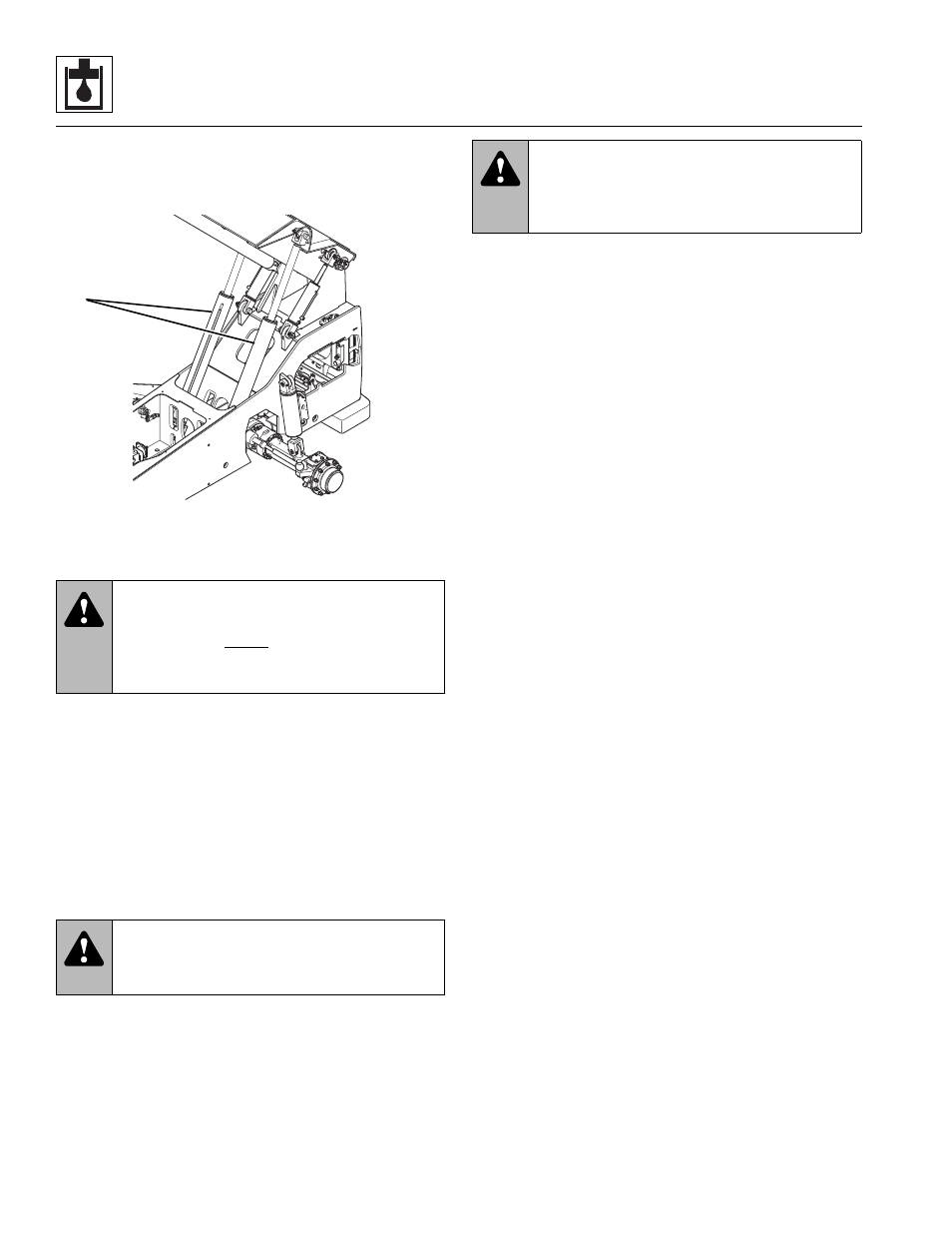
Lift/Lower Cylinder
The lift/lower cylinders (Fig. 8-74, 1) are anchored to the
underside of the outer boom and to the vehicle frame.
Figure 8-74 Lift/Lower Cylinders
a. Lift/Lower Cylinder Removal
1. Park the vehicle on a firm, level surface, fully retract
all hydraulic cylinders, ground the attachment (if
any), place the travel select lever in (N) NEUTRAL,
place the neutral lock lever in the (N) NEUTRAL LOCK
position, engage the park brake switch, raise and
support the boom to allow removal of the lift/lower
cylinder and shut the engine OFF.
2. Place an Accident Prevention Tag on both the
ignition key switch and the steering wheel, stating
that the vehicle should not be operated. Refer to
Section 1.5, “Accident Prevention Tag Usage.”
3. Unlock and open the rear door. Allow the hydraulic
fluid to cool.
4. Label or otherwise mark the lift/lower cylinder hydraulic
hoses. Disconnect and cap all hoses and fittings.
5. Attach a sling to the lift/lower cylinder and to a
suitable hoist or overhead crane. Support the lift/
lower cylinder in the sling.
6. Remove the locknut, capscrew and rod end mount pin
from the cylinder. Allow the cylinder to retract so that
it can clear the mounting bracket on the outer boom.
7. Remove the locknut, capscrew and base end mount
pin from the cylinder.
8. Safely and carefully, remove the lift/lower cylinder
from the vehicle. Wipe up any hydraulic fluid spillage
in, on, near and around the vehicle.
b. Lift/Lower Cylinder Disassembly
Note: An additional o-ring may be included at the base
of the cylinder rod. This additional o-ring may be discarded,
as it served only in a temporarily protective role.
1. Clean the lift/lower cylinder (Fig. 8-75, 1) with a
suitable cleaner. Remove all dirt, debris and grease
from the cylinder.
IMPORTANT: Avoid using excess force when clamping
the cylinder in a vise. Apply only enough force to hold the
cylinder securely. Excessive force can damage the
cylinder tube (Fig. 8-75, 2).
2. Secure the lift/lower cylinder in a soft-jawed vise or
other acceptable holding equipment if possible.
3. Slowly remove the counterbalance valve (Fig. 8-75, 3)
and pilot-operated check valve (4) from the tube (2).
IMPORTANT: DO NOT tamper with or attempt to reset
the counterbalance valve cartridge. If adjustment or
replacement is necessary, replace the counterbalance
valve with a new part.
4. Extend the rod (Fig. 8-75, 5) as required to allow
access to the base of the cylinder.
IMPORTANT: Protect the finish on the rod at all times.
Damage to the surface of the rod can cause seal failure.
5. Using a pin spanner wrench, unscrew the locking collar
(Fig. 8-75, 6) from the tube (2). The locking collar
was originally torqued to 300-400 lb-ft
(407-542 Nm), so a considerable amount of force is
required. Carefully slide the locking collar (6) and the
head gland (7) down along the rod toward the eyelet
end, away from the cylinder tube (2).
WARNING:
DO NOT get under a raised
boom unless the boom is blocked up. Always
block the boom before doing any servicing that
requires the boom to be up. Unexpected lowering
of the boom may cause death or serious injury.
WARNING:
Hot hydraulic fluid can
cause severe burns. Wait for hydraulic fluid to
cool before servicing any hydraulic component.
MA9290
1
WARNING:
Escaping hydraulic fluid
under pressure can penetrate the skin, causing
death or serious injury. Relieve hydraulic pressure
before servicing any hydraulic component.