SkyTrak 6042 Service Manual User Manual
Page 82
Boom
3.36
Model 6042 Legacy
Origin 7/02
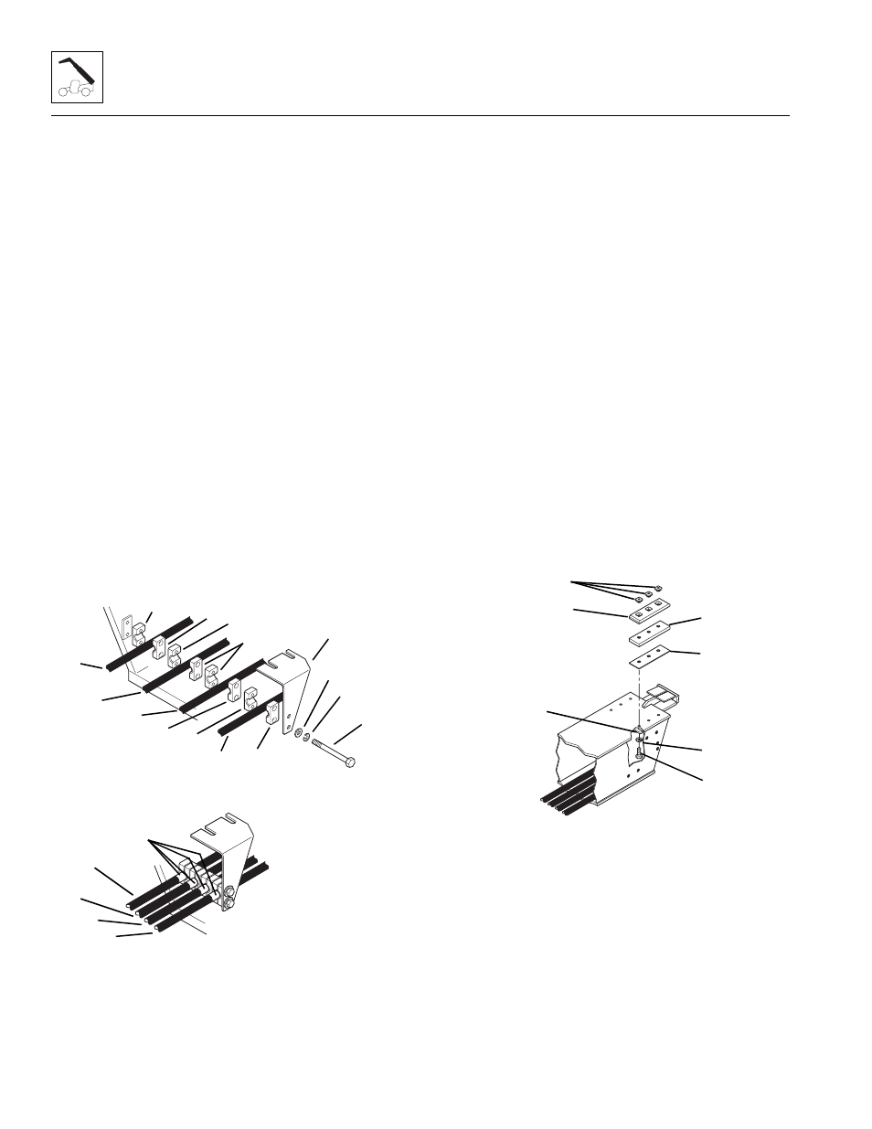
5. Keep the four hoses in line (left to right) as they
come out of the rear of the inner boom. Place a 5/16"
lockwasher (Fig. 3 -79, 1), saved, and a 5/16" flat
washer (2), saved, onto each 5/16-18 x 5" capscrew
(3), saved. Insert the capscrews through the hose
clamp support bracket (4), saved. Insert the
capscrews from the side as shown.
6. Place a 3/4" diameter hose clamp half (Fig. 3 -79, 5),
saved, onto the capscrews. Place the right auxiliary
hydraulic hose (6) and another 3/4" diameter hose
clamp half (5) onto the capscrews.
7. Place a 5/8" diameter hose clamp half (Fig. 3 -79, 7),
saved, the right attachment tilt hose (8) and another
5/8" diameter hose clamp half (7) onto the
capscrews.
8. Place two more 5/8" diameter hose clamp halves
(Fig. 3-79, 7), the left attachment tilt hose (9) and
another 5/8" diameter hose clamp half onto the
capscrews.
9. Place a 3/4" diameter hose clamp half (Fig. 3 -79, 5),
saved, the left auxiliary hydraulic hose (10) and
another 3/4" diameter hose clamp half (5) onto the
capscrews. Assemble the capscrews to the left side
of the inner boom. Tighten the capscrews only
enough to hold the hoses in place.
Figure 3-79 Attachment Tilt and Auxiliary Hydraulic Hose
Clamps Inside Inner Boom
10. Assemble the hose clamp support bracket to the top
of the inner boom:
Note: Shim ALL upper rear wear pads as needed to
maintain a total maximum gap of .06" (1,5 mm) at the
rear of the pads and maintain a total minimum gap of
.07-.13" (1,8 to 3,3 mm) in the vertical direction.
a. Place the wear pad inserts (Fig. 3-80, 1), saved,
into the cavities of the inner boom top left side
wear pad (2), saved.
b. Place the wear pad, spacer (Fig. 3-80, 3), saved,
and shims (4), saved if present, onto the inner
boom with the offset of the wear pad the same as
noted in disassembly.
c. Apply Loctite
®
242 threadlocker to the threads of
the 3/8-16 x 1-3/4" capscrews (Fig. 3-80, 5),
saved. Align the holes and secure the wear pad
and hose clamp support bracket (6) in place with
the capscrews (5) and 3/8" lockwashers (7),
saved. Be careful not to push the wear pad
inserts out of the wear pads.
d. Torque all wear pad mounting capscrews to
31 ±3 lb-ft (42 ±4 Nm).
e. Fill all wear pad cavities with a good grade of
lithium-based EP grease.
Figure 3-80 Inner Boom Upper Left Side Wear Pad
11. Position the attachment tilt and auxiliary hydraulic
hoses with the edge of the tape (Fig. 3 -79, 11) at the
hose clamps. Hold the hoses in this position, and
tighten the two capscrews securely to hold the hoses.
MH1630
9
11
5
10
2
3
1
6
7
8
4
5
6
7
7
8
9
10
5
5
MA10,0570
1
2
3
4
5
7
6