Transmission description, Transmission operation, Transmission serial number – SkyTrak 6042 Service Manual User Manual
Page 181: Warning
6.3
Model 6042 Legacy
Origin 7/02
Transmission: ZF 4 WG-98 TC
6.2
TRANSMISSION DESCRIPTION
Instructions in this section pertain mainly to general
specifications, towing, maintenance information, and
transmission removal and installation procedures. Internal
transmission service instructions and detailed specifications
are provided in the ZF 4 WG-98 TC Transmission Repair
Manual, OmniQuip P/N 8990455 (ZF P/N 5871 135 002).
The ZF 4 WG-98 TC Transmission used in this vehicle is
a four-speed configuration. The “intermediate drop”
designation refers to the relative top-to-bottom length of
the transmission case, chosen for its compatibility with
vehicle chassis and operating requirements. Intermediate
drop does not refer to an operational rpm shift or drop.
6.3
TRANSMISSION OPERATION
The transmission is mounted to the frame by front and
rear mounting brackets and rubber isolator pads. Power
from the engine is transmitted to the transmission by
means of a drive shaft, bolted to the engine flywheel and
a torque converter at the transmission input. The
transmission in turn transmits power to the drive shafts,
driving the front and rear axles.
The torque converter consists of three main components:
the impeller (driver), stator and turbine (driven) in an oil-
filled, enclosed housing. As the torque converter is driven
by the engine flywheel, the impeller (pump) wheel
rotates, forcing oil through the stator, which is held
stationary by the stator shaft bolted to the transmission
housing. This directs the moving oil onto the vanes of the
turbine (driven) wheel, causing the turbine wheel to rotate.
The turbine wheel is connected to the transmission input
shaft, and transfers power to the transmission. Oil from
the turbine wheel is then returned to the impeller wheel to
repeat the process. This process results in an increase in
the torque available at the transmission input shaft.
The transmission and torque converter are powered by
their own internal hydraulic (“transmission fluid”) systems,
separate from the vehicle hydraulic system. Pressurized
oil for the valve control circuits and torque converter is
supplied by a pump located at the rear of the
transmission. The pump is driven by the central shaft,
which in turn is connected to the impeller of the torque
converter. The transmission is equipped with an external
oil cooler, mounted in the engine heat exchanger (radiator).
The transmission gear (“speed”) select lever, an electric
shift control, is located on the left side of the steering
column in the operator’s cab. Movement of the gear
select lever energizes the selected transmission shift
solenoid valves, which, in turn, direct the transmission
fluid under pressure to the selected forward or reverse
valve and to the designated range (gear or “speed”)
clutch. Several factors, including terrain, loading, engine
rpm, axle/wheel-end gearing and the selected
transmission gear, determine actual vehicle speed.
To engage the clutch, the gear select lever is placed in
the desired direction (forward or reverse) and range (gear
or “speed”) position. The gear select lever movement
energizes the selected direction and range (gear)
solenoids, allowing transmission fluid under pressure to
flow through tubes and passages to the selected clutch
shafts. Oil sealing rings are located on the clutch shaft;
these rings direct oil under pressure through a drilled
passageway in the shaft to a desired clutch. Hydraulic
pressure forces the piston and discs against the back-up
plate. Discs, with edge tangs, clamp against toothed
discs on the inner diameter, enabling the hub and the
clutch shaft to lock together and drive as a unit, providing
output power.
6.4
TRANSMISSION SERIAL NUMBER
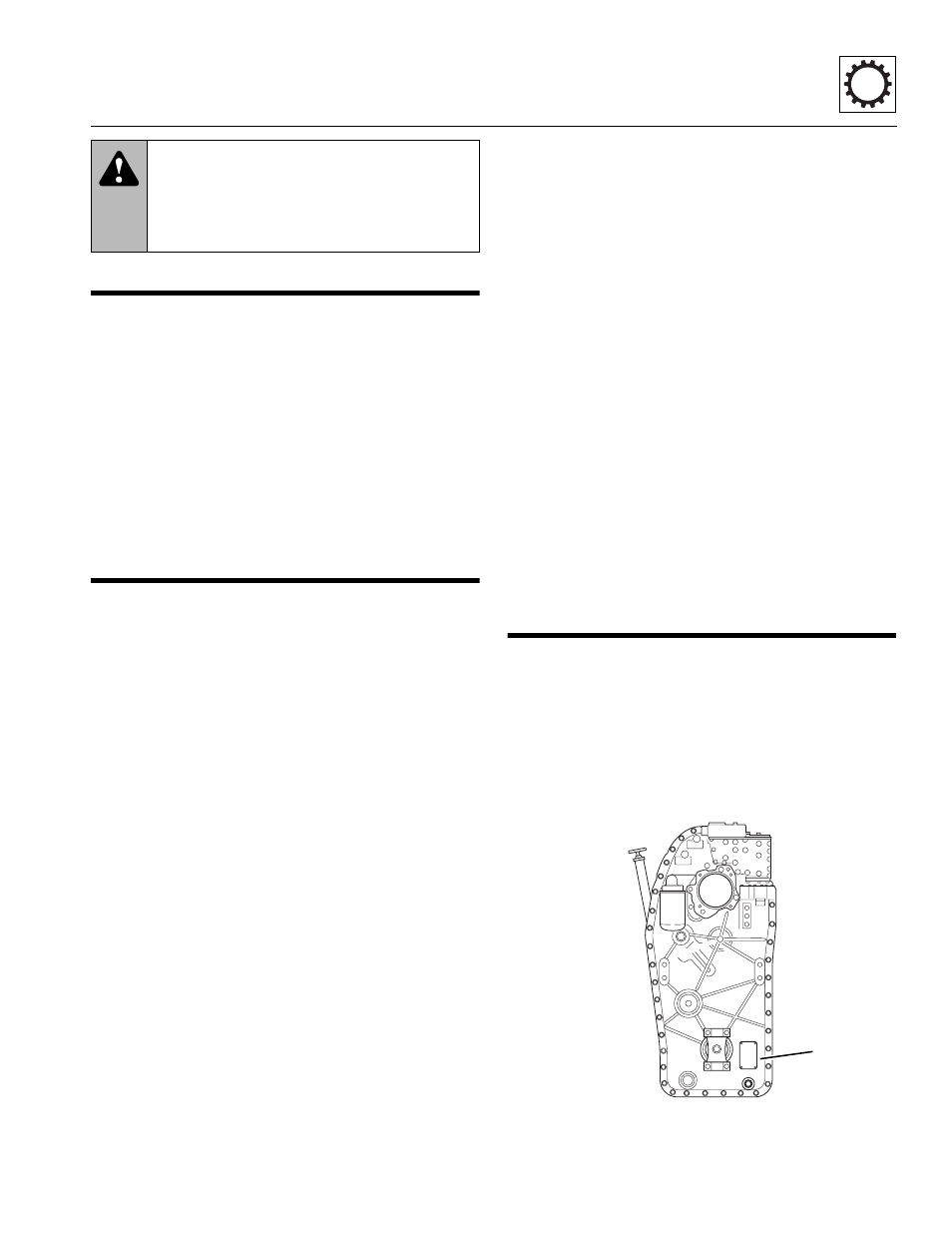
The transmission serial number plate (Fig. 6-1, 1) is
located on the pump side (front) of the transmission at the
bottom right, toward the vehicle frame. Information
specified on the serial number plate includes the
transmission model number, the transmission serial
number and other data. Information on the serial number
plate is required in correspondence regarding the
transmission.
Figure 6-1 Transmission Serial Number Plate Location
WARNING:
DO NOT service the vehicle
without following all safety precautions as
outlined in the “Safety Practices” section of this
manual. Failure to follow the safety practices
may result in death or serious injury.
MA8940
1