SkyTrak 6042 Service Manual User Manual
Page 106
Boom
3.60
Model 6042 Legacy
Origin 7/02
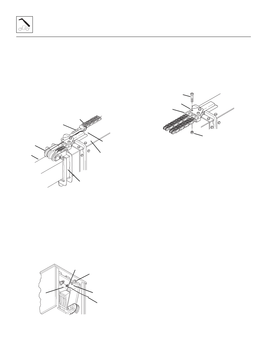
11. Lay the new extend chain (Fig. 3-133, 1) on top of
the outer boom (2) with the threaded clevis (3)
toward the front of the boom.
12. Attach the wire (Fig. 3-133, 4) to the threaded clevis
(3) of the new extend chain. Loop the wire through
the clevis and twist together to form a loop.
13. Pull the extend chain forward and place over the
right side of the chain sheave (Fig. 3-133, 5). Guide
the wire and the threaded clevis into the boom by
placing the threaded clevis under the chain sheave,
and between the top of the inner boom (6) and the
intermediate boom (7).
Figure 3-133 Extend Chain Reassembly
14. While one person guides the extend chain into the
front of the boom, a second person should pull the
wire (Fig. 3 -134, 1) and threaded clevis toward the
rear of the boom. Guide the threaded clevis (2) into
the hole in the anchor plate (3).
15. Place the 3/4" flat washer (Fig. 3-134, 4), saved,
onto the threaded end of the threaded clevis and
assemble a new 3/4-16 elastic locknut (5). Thread
the elastic locknut onto the threaded clevis until the
threads are flush with the top of the nut.
Figure 3-134 Threaded Clevis to Anchor Plate
16. Pull the anchor clevis (Fig. 3 -135, 1) up around the
double chain sheave and position the clevis between
the yoke plates (2).
17. Coat the hex-socket head capscrew (Fig. 3 -135, 3),
saved, with anti-seize compound. Insert the capscrew
through the yoke plates and clevis and secure in
place with a new 3/8-16 elastic locknut (4). Tighten
securely; but the chain clevis must pivot freely.
Figure 3-135 Extend Chain Clevis and Yoke Plates
18. Cut the loop in the wire and remove the wire from
the clevis.
19. Repeat Section 3.4.5, a. “Extend Chains Removal
and Replacement” starting with Step 5, to remove
and replace the left side extend chain.
20. At the rear of the boom, tighten the two elastic
locknuts (Fig. 3-134, 5) on the extend chain clevis’
until the amount of threads protruding beyond each
elastic locknut is the same as the measurement
recorded during removal of the extend chains.
21. Adjust extend chain tension. (Refer to Section 3.4.4,
“Boom Chain Tension Adjustment.”)
22. After adjustment is complete, assemble the rear cover
to the rear of the outer boom. At the rear of the outer
boom (Fig. 3 -136, 1), position the rear cover (2) in
place. Secure the cover in place with the 5/16" flat
washer (3), saved, 5/16" internal-tooth lockwasher
(4), saved, and thumbscrew (5), saved. Insert the
thumbscrew through the bottom of the outer boom
and into the rear cover. Tighten the thumbscrew
securely to hold the cover in place.
SH1851
3
4
1
2
5
6
7
~
~
SH1861
3
5
1
2
4
SH1810
1
2
3
4