10 swing carriage (optional) – SkyTrak 6042 Service Manual User Manual
Page 357
8.125
Model 6042 Legacy
Origin 7/02
Hydraulic System
IMPORTANT: Use a suitable installation tool or
compression sleeve to help prevent twisting or damaging
the seals and o-rings when installing the piston
(Fig. 8-82, 12) and head gland (9) into the cylinder.
When sliding the rod and piston assembly in the tube,
DO NOT damage the piston by scraping it against the
threads in the tube. Keep the rod in line with the tube to
prevent binding.
14. Keep the rod (Fig. 8-82, 10) straight and carefully
insert the rod into the tube (2). Avoid scratching,
nicking or damaging the tube while installing the rod.
15. Begin threading the head gland (Fig. 8-82, 9) into
the tube (2). Place the locking insert (8) in its hole in
the head gland threads just before the hole is
threaded into the tube. Use a suitable pin spanner
wrench to thread the head gland (9) completely into
the tube (2). Torque the head gland to 300-400 lb-ft
(407-542 Nm).
16. Using new oiled o-rings, thread the two pilot-operated
check valves (Fig. 8-82, 3), the pressure reducing
valve (4) and the five solenoid valves (5 and 6) into
the manifold block (7). Torque the five solenoid
cartridges (5 and 6) to 25-30 lb-ft (34-41 Nm).
Torque the check valves (3) and the pressure
reducing valve (4) to 35-40 lb-ft (47-54 Nm). Place
the solenoid coils on the cartridges and torque the
solenoid nuts to 4-6 lb-ft (5-8 Nm).
17. Test the cylinder at low operating pressure [100 psi
(7 bar)] to verify that the piston and rod move freely
in both directions.
18. Increase the operating pressure to the maximum for
the cylinder [4,000 psi (275 bar)] and check for
external leakage and for free movement in both
directions.
19. Retract the piston fully.
f.
Stabilizer Cylinder Installation
1. Lubricate the cylinder pins with multi-purpose,
lithium-based grease.
2. Use a sling and hoist or other suitable lifting device
to help install the cylinder. Orient the cylinder with
the cylinder eyelet on top and the rod eyelet on the
bottom.
3. Install the upper cylinder pin. Drive the lubricated
cylinder pin through the cylinder eyelet, frame mount
and self-aligning bearing. Secure the pin with a
capscrew and hex-locknut. Torque to 18 lb-ft (24 Nm).
4. Use new flat-faced oiled o-rings when installing the
upper and lower hydraulic hoses. Install and tighten
the hoses onto the appropriate fittings on the
manifold.
g. Stabilizer Cylinder Pressure Checking and
Circuit Bleeding
1. Attach a 4,000 psi (276 bar) gauge to the test fitting
on the main control valve to test the system
pressure. Pressure readings should be
3,000 ±100
psi (207 ±7 bar). Refer to Section 8.7, “Hydraulic
System Testing.” To check the cylinder pressure,
consult the factory.
2. Start the vehicle. Level the frame.
3. Sway the vehicle fully left. Hold the joystick at full
sway left for several seconds, then sway the vehicle
fully right and hold the joystick at full sway right for
several seconds. Observe the readings on the gauge
during the frame sway operations.
4. Level the frame. While leveling the frame, check the
pressure reading on the gauge.
5. Repeat Steps 3-4 five times.
8.13.10
Swing Carriage (Optional)
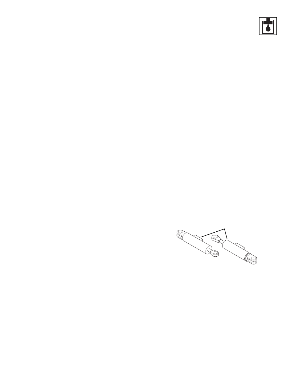
The optional swing carriage provides a way to swing the
carriage attachment from side-to-side. The swing carriage
includes two cylinders (Fig. 8-83, 1) that operate together
to provide the side-to-side motion.
Figure 8-83 Swing Carriage Cylinders
a. Swing Carriage Cylinder Removal
1. Level the boom (place the boom in a horizontal
position).
2. Swing the carriage to the centered position.
3. Lower the boom until the carriage is resting firmly on
the ground.
4. Place the travel select lever in (N) NEUTRAL, place
the neutral lock lever in the (N) NEUTRAL LOCK
position, engage the park brake switch and shut the
engine OFF.
MT2450
1