Fig. 3-38, Fig. 3-39 – SkyTrak 6042 Service Manual User Manual
Page 63
3.17
Model 6042 Legacy
Origin 7/02
Boom
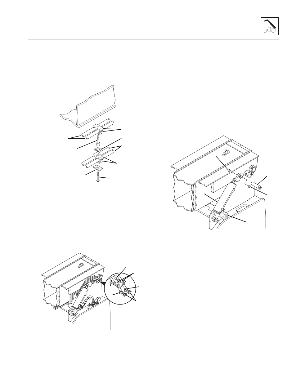
16. Label the attachment tilt tube assemblies (Fig. 3-38, 2)
located under the boom. Remove the stacking bolts
(6) holding the tube clamps (7), locking plates (8)
and attachment tilt tubes (2) to the underside of the
outer boom. Save the stacking bolts, clamps and
locking plates.
Figure 3-38 Auxiliary Hydraulic and Attachment Tilt Tubes
17. Remove the bulkhead nuts (Fig. 3-39, 3) from the
attachment tilt tube assemblies (4). Lift the tube out of
the bulkhead plate and re-thread the nut onto the
end of the tube. Cap both ends and remove the
tubes from the boom.
18. Inspect all tubes (Fig. 3-38, 1 and 2) for kinks or
crushed areas. If any kinks or crushed areas exist,
replace the damaged tube or tubes.
Figure 3-39 Remove Bulkhead Nuts From Auxiliary
Hydraulic and Attachment Tilt Tubes
19. Remove the capscrew (Fig. 3 -40, 1) and elastic
locknut (2) holding the upper slave cylinder pivot pin
(3) to the outer boom. Securely block (4) the slave
cylinder (5) in position. Remove the pivot pin from the
pin mount by pulling the pin out. It may be necessary
to use an appropriate puller threaded into the pivot
pin to remove the pin. Discard the elastic locknut and
retain the capscrew.
20. Inspect the pivot pin (Fig. 3-40, 3) for nicks or damage.
If the pin is damaged, it must be replaced.
21. Repeat Steps 19-20 to remove the other upper slave
cylinder pivot pin.
Figure 3-40 Upper Slave Cylinder Pivot Pin
MH1191
1
2
3
4
8
7
6
5
MA9810
1
3
4
2
3
4
MA9760
1
2
3
4
5