SkyTrak 6042 Service Manual User Manual
Page 54
Boom
3.8
Model 6042 Legacy
Origin 7/02
Note: If replacing the inner boom assembly with a new
inner boom, the quick attach assembly and the attachment
tilt cylinder should be removed at this time.
If the inner boom is not to be replaced, the quick attach
assembly and attachment tilt cylinder can remain in
place. Proceed to Step 34.
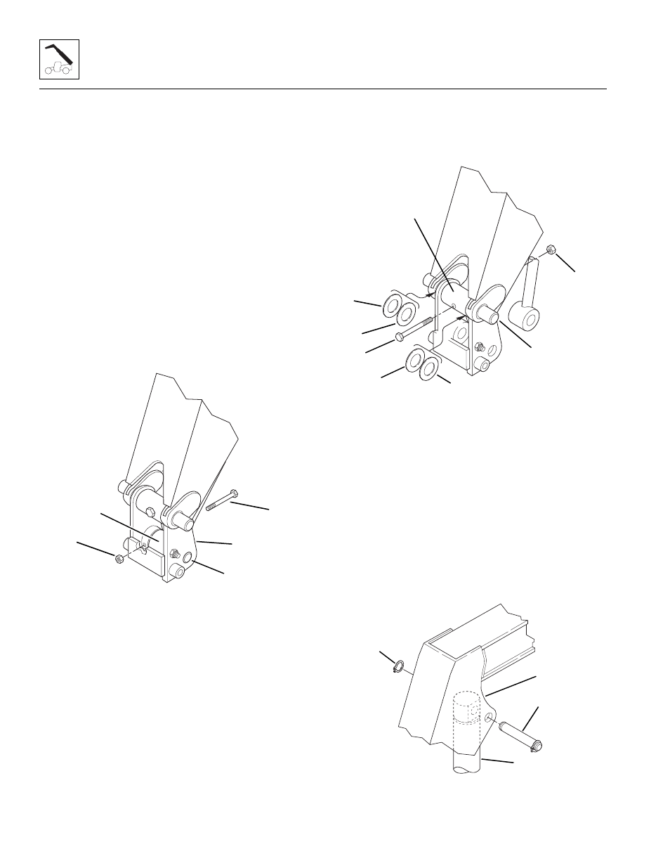
25. Remove the elastic locknut (Fig. 3-13, 1) and
capscrew (2) holding the attachment tilt cylinder rod
end pin (3) to the quick attach assembly (4). Save
the capscrew and discard the elastic locknut.
26. Support the rod end of the attachment tilt cylinder
(Fig. 3-13, 5). Use a brass punch and a rawhide
hammer to remove the rod end pin (3) from the quick
attach assembly.
27. Inspect the pin (Fig. 3 -13, 3) for nicks or surface
corrosion. Use fine emery cloth to fix minor nicks or
corrosion. If damaged and if it cannot be repaired,
the pin must be replaced.
Figure 3-13 Attachment Tilt Cylinder Rod
End Pin Removal
28. Remove the elastic locknut (Fig. 3-14, 1) and
capscrew (2) holding the quick attach pivot pin (3) to
the quick attach assembly (4). Save the capscrew
and discard the elastic locknut. Place a support
under the quick attach assembly to prevent it from
dropping when the pivot pin is removed.
29. Use a brass punch and a rawhide hammer to
remove the quick attach pivot pin (Fig. 3 -14, 3) from
the quick attach assembly and the bushings in the
gooseneck. Record the location and quantity of the
shim washers (5 and 6) as the pin is being removed.
Save the washers (5 and 6) from each side of the
quick attach.
30. Inspect the pin for nicks or surface corrosion. Use
fine emery cloth to repair minor nicks or corrosion. If
damaged and if it cannot be repaired, the pin must
be replaced.
Figure 3- 14 Quick Attach Pivot Pin Removal
Note: The attachment tilt cylinder is heavy. Use a hoist
and sling to support the attachment tilt cylinder when the
base end pin is removed.
31. Remove the retaining ring (Fig. 3-15, 1) from one
side of the base end pivot pin (2). Save the retaining
ring. Use a brass punch and a rawhide hammer to
remove the base end pivot pin from the inner boom
gooseneck (3).
32. Inspect the pin for nicks or surface corrosion. Use
fine emery cloth to repair minor nicks or corrosion. If
damaged and if it cannot be repaired, the pin must
be replaced.
Figure 3-15 Attachment Tilt Cylinder Removal
MH0940
1
5
2
4
3
~
MH0950
5
4
3
2
1
5
6
6
~
MH0960
1
2
3
4