SkyTrak 6042 Service Manual User Manual
Page 309
8.77
Model 6042 Legacy
Origin 7/02
Hydraulic System
c. Main Control Valve Disassembly
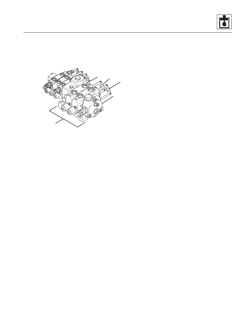
This section covers the disassembly of the other half
(Fig. 8-44, 1) of the main control valve, including the
outlet (2), lift/lower (3), extend/retract (4) and mid-inlet/
outlet (5) sections of the main control valve.
Figure 8-44 Main Control Valve
1. To disassemble the outlet, lift/lower, extend/retract
and mid-inlet/outlet sections of the main control
valve (Fig. 8-43, 1), remove the three nuts (2 and 3)
from the end of the three tie rods (4 and 5). Pull the
tie rods out through the section assemblies.
2. Disassemble each section as required.
Some sections include a pre-adjusted relief valve that
regulates pressure in a specific circuit.
IMPORTANT: DO NOT adjust any of the relief valve
assemblies! Tampering with a relief valve will irrevocably
alter pressure in the affected circuit, requiring re-calibration
or a new relief valve assembly.
Disassemble the Extend/Retract and Lift/Lower Outlet
Section
1. Carefully separate the outlet section (Fig. 8-43, 6)
from the lift/lower section (28). Avoid dislodging or
losing the shuttle (29), spring (30) and poppet (31) in
the lift/lower section.
2. Remove the o-ring (Fig. 8-43, 7) from between the
two sections.
3. Remove the shut-off plug (Fig. 8 -43, 8) from the
outlet section (6).
4. Remove the remaining plugs (Fig. 8-43, 9, 11 and
13) and o-rings (10, 12 and 14).
Disassemble the Main Relief Valve (Outlet Section)
The main relief valve (Fig. 8-43, 15) is part of the outlet
section (6). The valve is preset at 3,500 psi (241 bar).
1. Remove the relief valve (Fig. 8-43, 15) from the
outlet section (6).
2. Remove the o-ring (Fig. 8 -43, 16) from the relief
valve (15).
3. Grip the relief valve body (Fig. 8-43, 17) with a
suitable tool and use another tool to remove the
nut (18), revealing an o-ring (19) and the adjustment
screw (20).
4. Remove the nut (Fig. 8-43, 21), o-ring (22), shim (23),
spring (24), spring retainer (25) and poppet (26).
5. Remove the plug (Fig. 8-43, 27) from the body (17).
Disassemble the Lift/Lower Section
1. Carefully separate the lift/lower section (Fig. 8-43, 28)
from the extend/retract section (32). Avoid dislodging
or losing the shuttle (33), spring (34) and poppet (35)
in the extend/retract section.
2. Remove the o-ring (Fig. 8-43, 36) from between the
two sections. Remove the shuttle (29), spring (30)
and poppet (31) from the lift/lower section (28).
3. Remove both socket head capscrews (Fig. 8-43, 37)
securing the cable retainer assembly (38) to the lift/
lower section (28).
4. Remove the retainer (Fig. 8-43, 39), both
sleeves (40), another retainer (39), wiper (41) and
o-ring (42) from the cable retainer assembly 38).
5. Remove both socket head capscrews (Fig. 8-43, 43)
securing the end mechanism (44) to the lift/lower
section (28).
6. Remove the spool cap (Fig. 8-43, 45), retainer (39),
spool end (46), spring seat (47), spring (48), another
spring seat (49), wiper (50) and o-ring (51) from the end
mechanism (44).
MA10,0200
1
2
3
4
5