SkyTrak 6042 Service Manual User Manual
Page 503
9.133
Model 6042 Legacy
Origin 7/02
Electrical System
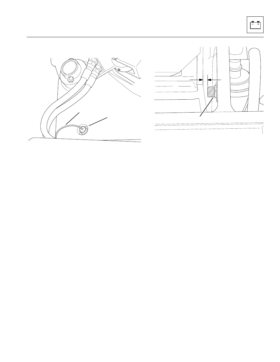
2. Disconnect the boom lift sensor electrical connector
(Fig. 9-132, 2) from the engine harness connector.
Figure 9-132 Boom Lift Sensor Location
3. Loosen and remove the sensor inside locknut
(Fig. 9-133, 1)
4. Remove sensor from the outside of boom frame
Figure 9-133 Boom Lift Sensor Adjustment
b. Boom Lift Sensor Installation
1. Install boom lift sensor (Fig. 9-132, 1) through
outside of boom frame.
2. Install inside locknut (Fig. 9 -133, 1) onto sensor.
3. Measure the clearance between the sensor and
frame, and adjust sensor distance to .12” (3,05 mm)
(Fig. 9 -133, 2) and tighten locknut (1).
4. Connect the negative (–) battery cable at the
negative battery terminal (Fig. 9-131, 1).
1
2
MH2930
MH2920
1
2