Throttle pedal replacement – SkyTrak 6042 Service Manual User Manual
Page 131
4.11
Model 6042 Legacy
Origin 7/02
Cab and Covers
4.3.5
Throttle Pedal Replacement
a. Throttle Pedal Removal
1. Park the vehicle on a firm, level surface. Level the
vehicle, ground the attachment, place the travel
select lever in the (N) NEUTRAL position, place the
neutral lock lever in the (N) NEUTRAL LOCK
position, engage the parking brake switch and shut
the engine OFF.
2. Place an Accident Prevention Tag on both the
ignition key switch and steering wheel, stating that
the vehicle should not be operated. (Refer to Section
1.5, “Accident Prevention Tag Usage.”)
3. Disconnect the battery negative (-) cable at the
battery negative (-) terminal.
4. Remove the extension spring (Fig. 4-16, 1) from the
throttle pedal assembly (2).
5. Remove the clip (Fig. 4-16, 3) and clevis pin (4)
securing the throttle cable (5) to the throttle pedal
assembly (2).
6. Remove two locknuts (Fig. 4-16, 6) and cable
clamp (7). Remove the throttle cable (5) from the
throttle pedal assembly (2).
7. Loosen the two nuts (Fig. 4-16, 8) on the u-bolt (9)
at the pedal pivot. Loosen the two locknuts (10) to
allow the cable support bracket (11) to pivot.
8. Remove three 1/4-20 x 1-1/4" hex-head capscrews
(Fig. 4-16, 12), three 1/4" lockwashers (13) and
three 1/4" SAE flat washers (14) securing the throttle
pedal assembly (2) to the cab floor (15).
9. Remove the throttle pedal assembly (Fig. 4-16, 2)
from the cab.
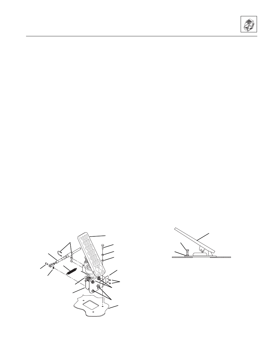
Figure 4- 16 Throttle Pedal Mounting Arrangement
b. Throttle Pedal Installation
1. Align the throttle pedal assembly (Fig. 4 -16, 2) with
its mount holes in the cab floor (15).
2. Install three 1/4-20 x 1-1/4" hex-head capscrews
(Fig. 4 -16, 12), three 1/4" lockwashers (13) and
three 1/4" SAE flat washers (14) securing the throttle
pedal assembly to the cab floor (15). Torque the
capscrews to 9 lb-ft (12 Nm).
3. Position the lower part of the throttle pedal assembly
(Fig. 4 -16, 16) so it is aligned to the pedal as shown
and tighten the two nuts (8) on the u-bolt (9) to
secure in place. Position the cable support
bracket (11) as shown and tighten the two
locknuts (10) to secure in place.
4. Install the clevis pin (Fig. 4-16, 4) and clip (3)
through the end of the throttle cable (5) to attach it to
the throttle pedal lever (17).
5. Install the cable clamp (7) to the cable support
bracket (11) using two locknuts (6).
6. Attach one end of the extension spring (Fig. 4-16, 1)
to the throttle pedal lever (17) beneath the pedal.
Attach the other end of the spring to the cable
clamp (7).
7. Connect the battery negative (-) cable.
c. Throttle Adjustment
1. From within the cab, lightly depress the accelerator
pedal (Fig. 4-17, 1) to the full-throttle position. As
needed, adjust the limit-stop screw (2) until it touches
the pedal. Tighten the locknut (3) to 120-125 lb/in
(13,6-14,1 Nm).
Figure 4-17 Adjust the Throttle Limit-stop Screw
IMPORTANT: During the full throttle check:
• DO NOT operate any hydraulic function.
• DO NOT steer or apply any pressure to the
steering wheel.
• Keep the transmission in (N) NEUTRAL.
2. Check the engine rpm at full throttle. If the rpm is not
2600-2800 rpm, readjust the throttle limit-stop screw
at the throttle pedal within the cab.
MA10,0630
3
5
1
11
7
6
2
4
8
10
12
13
14
15
17
16
9
MA10,0640
2
1
3