SkyTrak 6042 Service Manual User Manual
Page 64
Boom
3.18
Model 6042 Legacy
Origin 7/02
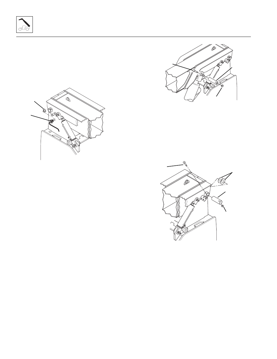
22. On the right side boom pivot mounting plate, locate
the boom sensor (Fig. 3-41, 1). Remove the hex nut (2)
on the inside of the mounting plate. Remove the boom
sensor from the outside of the plate, re-thread the
nut onto the sensor and allow the sensor to rest on
top of the frame, next to the mounting plate. The sensor
can remain connected to the harness.
Figure 3-41 Boom Sensor
Note: Use a hoist capable of lifting 5,000 lbs (2268 kg) and
two slings. Place the slings around the outer boom. The
slings should be placed far enough apart on the outer boom
so the boom will balance when the boom lift/lower cylinder
mounting pins and pivot pins are removed in the following
steps.
23. Remove the capscrew (Fig. 3-42, 1) and elastic
locknut (2) holding the upper lift/lower cylinder pivot
pin (3) to the outer boom. Securely block the lift/lower
cylinder in position. Remove the pivot pin from the pin
mount by pulling the pin out. It may be necessary to use
an appropriate puller threaded into the pivot pin to
remove the pin. Discard the elastic locknut and retain
the capscrew.
24. Inspect the pivot pin (Fig. 3 -42, 3) for nicks or
damage. If the pin is damaged, it must be replaced.
25. Repeat Steps 23 and 24 to remove the other lift/lower
cylinder.
Figure 3-42 Lift/Lower Cylinder Pivot Pins
26. Remove the capscrews (Fig. 3-43, 1) and elastic
locknuts (2) holding the boom pivot pins (3) to the
frame. Use a brass punch and a rawhide hammer to
remove the pivot pins from the frame. While removing
the pins, note the location, quantity and size of the
shims (4) between the outer boom and frame.
Figure 3-43 Outer Boom Pivot Pins
MA9960
1
2
MA9750
1
2
3
MA9900
1
4
3
2