SkyTrak 6042 Service Manual User Manual
Page 58
Boom
3.12
Model 6042 Legacy
Origin 7/02
10. Pull the hose reel with hoses out the back of the
intermediate boom. Allow the hose reel assembly to
slide down the hoses and rest it on the floor.
11. Label and remove the hoses from the hose reel. The
center bolt (Fig. 3-25, 1) can remain in place to hold
the hose reel and side plates together.
a. Remove the 3/8-16 elastic locknut (Fig. 3-25, 2)
and 3/8" flat washer (3) from the lower retaining
shoulder bolt (4). While pulling the shoulder bolt
out, catch the spacers (5) from between the
plates as the bolt is removed. Pull the bolt out far
enough to remove the hoses from the hose reel.
b. After the hoses are removed from behind the
lower retaining bolt, insert the shoulder bolt
(Fig. 3-25, 4) through the plates, inserting the
spacers (5) between the plates as the bolt is
inserted. Reassemble the 3/8" flat washer (3)
and 3/8-16 elastic locknut (2) to hold the shoulder
bolt in place. DO NOT fully tighten at this time.
c. Remove the 1/2-13 elastic locknut (Fig. 3-25, 6)
from the upper retaining capscrew (7). While
pulling the capscrew out, catch the spacers (8)
from between the plates as the capscrew is
removed. Pull the capscrew out far enough to
remove the hoses from the hose reel. Make sure
that spacer (9) and washer (10) remain in place
between the inside two plates (11) of the hose
reel assembly.
d. After the hoses are removed, insert the capscrew
(Fig. 3-25, 7) through the plates, inserting the
spacers (8) between the plates as the capscrew
is inserted. Reassemble the 1/2-13 elastic
locknut (6) to hold the capscrew in place.
Figure 3-25 Hose Reel Retaining Hardware
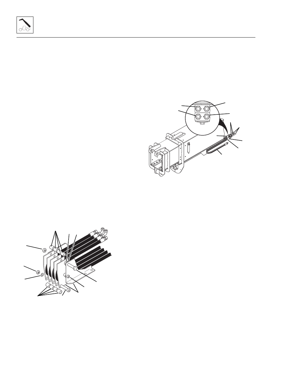
12. At the front of the outer boom, label and remove the
auxiliary hoses (Fig. 3 -26, 1 and 2) from the tube
assemblies (3) at the mounting plate. Plug the hose
ends and cap tube ends.
13. Label and remove the attachment tilt hoses
(Fig. 3-26, 4 and 5) from the tube assemblies (6) at
the mounting plate. Plug the hose ends and cap tube
ends.
Figure 3-26 Attachment Tilt and Auxiliary Hydraulic Hose
14. Pull the hose ends out from between the
intermediate boom and the outer boom and out the
rear of the boom.
15. Support the front of the extend/retract cylinder.
16. Remove the retaining ring (Fig. 3-27, 1) from one
side of the extend/retract cylinder rod end mounting
pin (2). Use a brass punch and a rawhide hammer to
remove the rod end pin from the mounting ears (3)
on the intermediate boom.
17. Inspect the pin (Fig. 3-27, 2) for wear or damage.
Use fine emery cloth to repair minor nicks or
corrosion. If the pin is damaged, replace it. Save the
retaining ring.
MH1491
1
2
8
3
4
5
6
7
9 10
11
MA9890
4
6
FRONT
3
5
2
5
1
4
2
1