E (fig. 9-69 – SkyTrak 6042 Service Manual User Manual
Page 467
9.97
Model 6042 Legacy
Origin 7/02
Electrical System
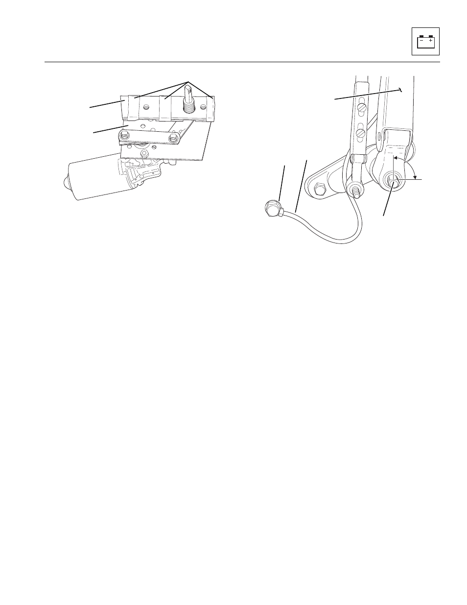
Figure 9-68 Front Wiper Motor and Spacer Plate
1. Install all required hardware to the motor assembly.
Align spacer (Fig. 9 -68, 1) and wiper motor bracket,
(2) and apply masking tape (3) in order to hold the
two components together during installation.
2. Align motor (Fig. 9 -66, 1) with cab mounting holes
and insert motor through cab.
3. Have an assistant insert gasket (Fig. 9 -66,13),
panto adapter (12) onto to the motor shaft (5). Insert
bolts (11) through front cab holes and thread into
motor housing. Tighten bolts.
4. Install metal washer (Fig. 9-66, 10) and metal hex
jam nut (9). Tighten metal hex jam nut. Install rubber
cap (8) and knurled driver (7) onto the motor shaft.
Note: Align the wiper blade arm with the flat on the
motor shaft to ensure wiper stroke covers window area,
and it does not swipe past the glass area.
Figure 9-69 Wiper Arm Alignment
5. Install wiper blade arm (Fig. 9-69, 1) at 90° from the
motor shaft flat (4).
6. Install internal-tooth lockwasher (Fig. 9-66, 4) and 1/4"
(3) and 3/8" (2) acorn nuts, and tighten.
7. Connect the cab harness connectors to windshield
wiper motor connectors.
8. Connect negative (–) battery cable at the negative
battery terminal (Fig. 9-67, 1).
9. Turn ignition key switch to the RUN position, and
operate windshield wiper in both LOW and HIGH
speeds to ensure proper operation and that correct
wiper travel is achieved.
10. Install right side defroster hose to the dash panel
hose connector.
11. If previously removed, install hydraulic hoses under
the dash. (Refer to Section 4.3.3, “Steering Column/
Valve Replacement.”)
12. Install the top right dash panel and lower dash panel.
1
MA8440
2
3
1
MA8450
2
3
90°
4