Iii-4.9 time1 (timer (no. 69)) 112, Time1 112, Timer 112 - 113 – West Control Solutions KS98-1 User Manual
Page 112: Timer 112
Inputs/outputs
Digital inputs
d1...d10
Condition inputs for switching over to the next step
reset
With input
reset = 1, output Step is set to 1 (only with individual function or at the first step of a cas-
cade). With the follow-up steps of a cascade, output y
1
= the
Casc input is set.
reset has the highest priority of all digital inputs.
Stop
With input
Stop = 1, the function block remains in the instantaneous step
(
y1 and z1 remain unchanged, unless reset is switched to 1).
skip
This input reacts only to a positive flank, i.e. on a change from 0 to 1. At this flank the STEP function switches
over to the next step without taking the status at the relevant d
i
input into account.
Analog input
Casc
Used for STEP function cascading. At the first STEP function of a cascade
Digital output
activ
activ =1 indicates that the STEP function is still in the active status or in reset.
activ =0 indicates that the STEP function has elapsed.
Analog output
Step
The value at
Step indicates the current step of the STEP function. With cascading, the value at Casc is
added to this value.
No parameters!
III-4.9
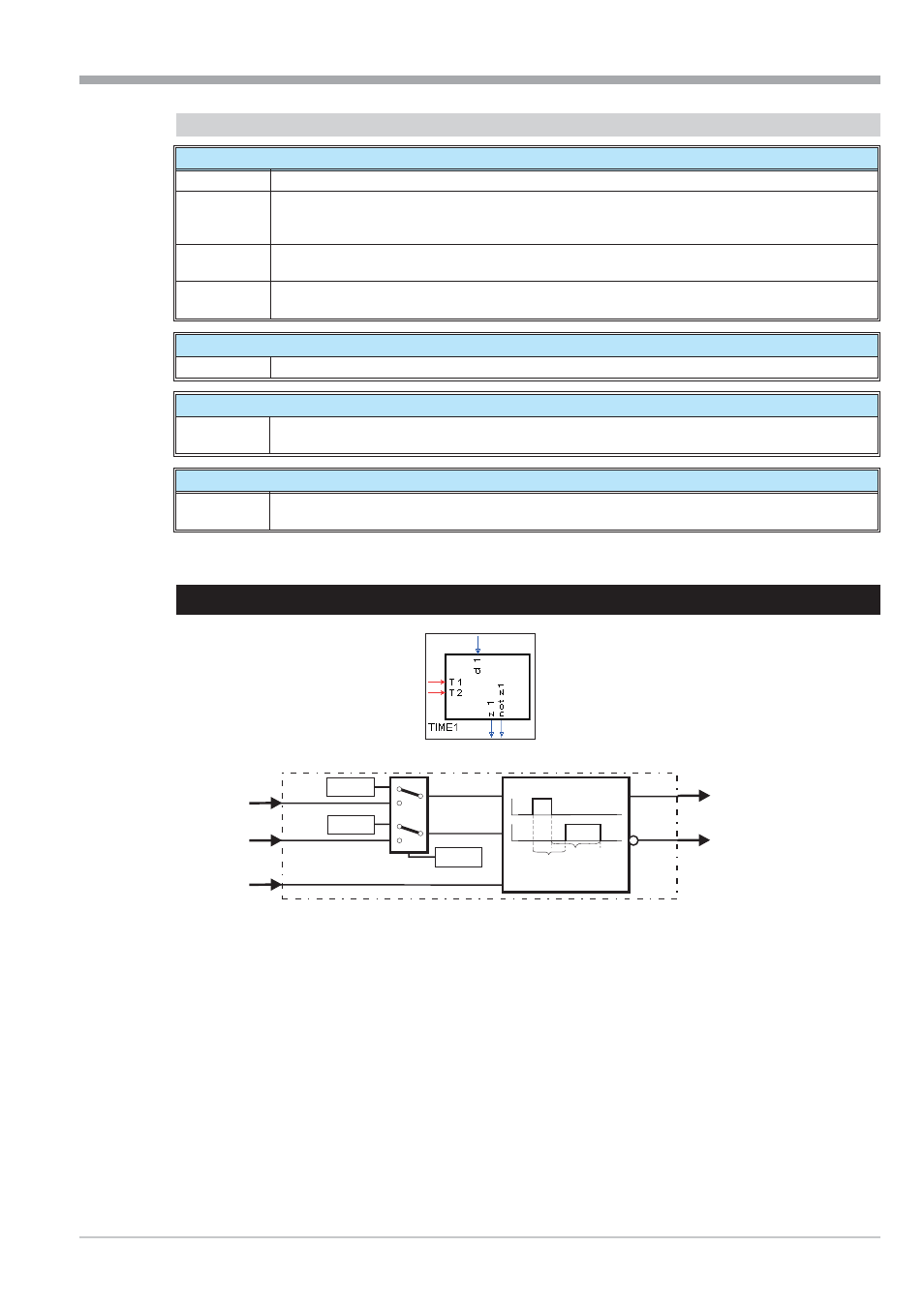
TIME1 (timer (No. 69))
The function outputs the change of signal status at d1 with a delay at z1.
The delay time can be adjusted separately for each change direction of the signal status! (positive and negative flank).
With change from 0 to 1 at input d1, output z1 is switched to 1 with a delay of time T1. With change from 1 to 0 at in -
put d1, output z1 is switched to 0 with a delay of time T2.
Time T1 is adjusted either as parameter T1 or read in via input T1.
Time T2 is adjusted either as parameter T2 or read in via input T2.
The time origin is selected via parameter Mode.
9499-040-82711
Logic functions
TIME1 (timer (No. 69))
III-112
T1
T2
d1
Mode
T1
T1
T2
t
t
T2
T1
T2
z1
not z1