Tool holder, tool mount, 1 t o ol d a tabase – HEIDENHAIN CNC Pilot 4290 V7.1 User Manual
Page 624
624
8.1 T
o
ol D
a
tabase
Mount type: If different tool mounts exist, the tool and the tool
location must have the same mount type (see MP 511, ...).
Influences the tool selection and tool placement in TURN PLUS.
The “Set up tool table” functions check whether the tool can be
used at the specified turret position.
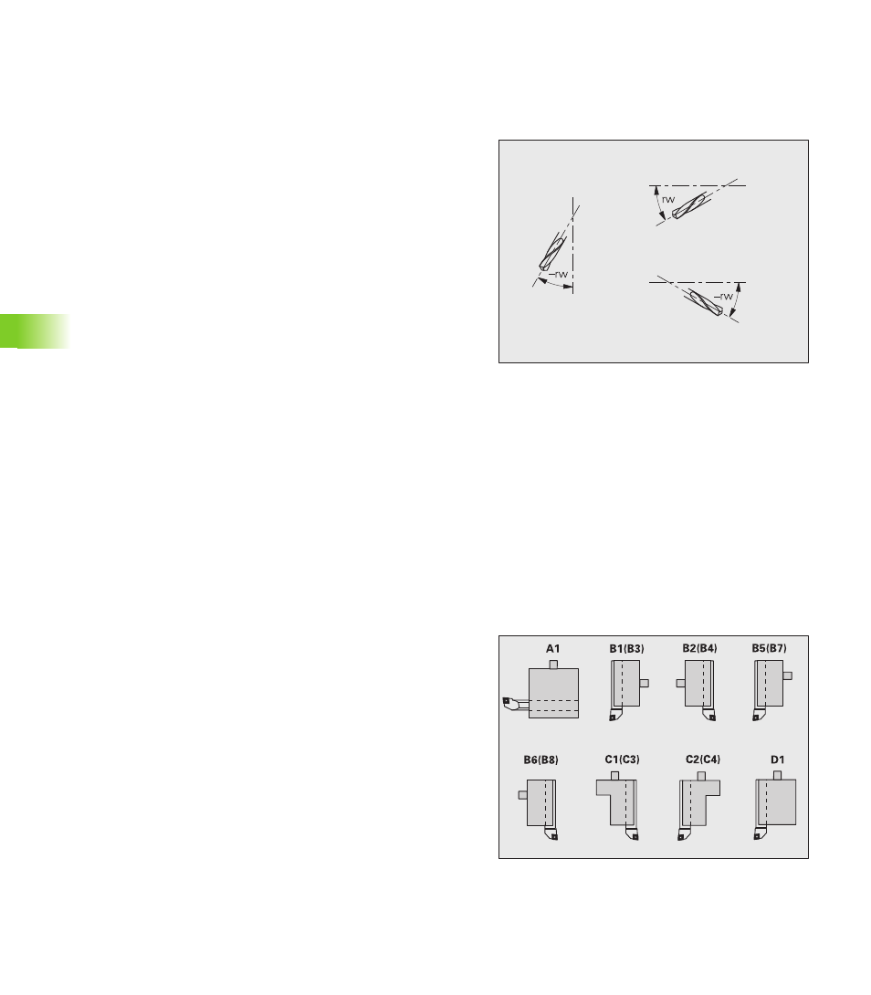
Angle of orientation (rw): Defines the deviation from the main
machining direction in the mathematically positive direction of
rotation (–90° < rw < +90°) – see illustration. TURN PLUS only uses
drilling and milling tools machining in direction of or at right angles
to the principal axis.
No of teeth: Used for “G93 feed rate per tooth”
Salient length (ax): For drilling and milling tools:
Axial tools: ax = distance between the tool reference point and the
top edge of the tool holder
Radial tools: ax = distance between the tool reference point and
the lower edge of the tool holder (also applies if the drill/mill is
chucked)
Tool holder, tool mount
Tool holder
The graphic tool representation functions in the simulation and control
graphics take account of the shape of the tool holder and the mounting
position on the tool carrier. When the tool holder type is not specified,
the CNC PILOT uses a simplified graphic representation.
Depending on the turret location, the CNC PILOT determines whether
the holder is mounted in an axial or radial position or whether an
adapter is used.
The CNC PILOT recognizes the following holders (designation of the
standard holder as per DIN 69 880):
Holder group 1
A1 boring bar holder
B1 right-hand, short design
B2 left-hand, short design
B3 right-hand, short design, overhead
B4 left-hand, short design, overhead
B5 right-hand, long design
B6 left-hand, long design
B7 right-hand, long design, overhead
B8 left-hand, long design, overhead
C1 right-hand
C2 left-hand
C3 right-hand, overhead
C4 left-hand, overhead
D1 Multicarrier