Entering contours machined with the c axis, 3 w o rk piece descr iption – HEIDENHAIN CNC Pilot 4290 V7.1 User Manual
Page 400
400
6.3 W
o
rk
piece Descr
iption
Entering contours machined with the C axis
You define standard forms with figures; regular linear or circular
figures or holes in patterns. To define complex contours, use the basic
elements “line” and “arc.”
Patterns
Linear hole patterns (drilling patterns)
Circular hole patterns (drilling patterns)
Linear figure patterns (milling contours)
Circular figure patterns (milling contours)
Figures
Circle (full circle)
Rectangle
Polygon
Slot, linear
Circular slot
You position patterns and figures on the
Front face (C-axis machining)
Lateral surface (C-axis machining)
Rear side (C-axis machining)
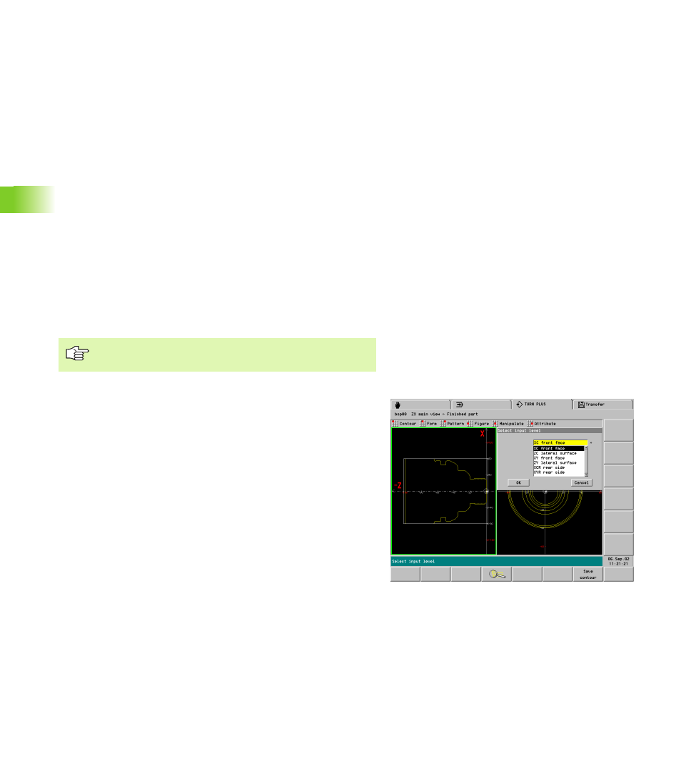
Selecting the input level
To define a C-axis contour, start by selecting the “input level” (front
face, lateral surface, rear face). Proceed as follows:
1. Select new window (it is not yet displayed):
U
Select the “Turning contour” window.
U
Select the pattern/figure from the “Pattern” or
“Figure” drop-down menu. TURN PLUS opens the
“Select input level” dialog box.
U
Select the input level: TURN PLUS opens the
corresponding window.
2. Select window (it is already displayed, but not activated):
U
Select the window with the PgUp/PgDn keys.
Define the complete turning contour before defining the
contours for C-axis machining.