7 overlay elements, Circular arc, Wedge/rounded wedge – HEIDENHAIN CNC Pilot 4290 V7.1 User Manual
Page 418: 7 ov er la y elements 6.7 overlay elements
418
6.7 Ov
er
la
y Elements
6.7 Overlay Elements
Select the standard overlay elements arc, wedge or pontoon, define
the element and superimpose it after the definition. When you are
superimposing a contour train, TURN PLUS uses the last active
contour train or the last overlay element defined (see “Integrating
overlay elements” on page 399).
Depending on the form of the supporting contour elements, there is a
Linear superimposition (“linear overlay”)
Circular superimposition (“circular overlay”)
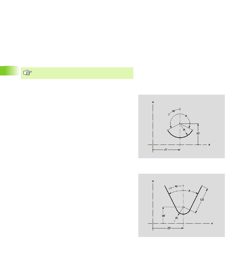
Circular arc
Circle center as reference.
Wedge/rounded wedge
Reference point: Wedge tip/center of rounding arc
The overlay positions can deviate from the supporting
contour element.
Parameters
XF
Reference point shift
ZF
Reference point shift
R
Radius of the arc
A
Angular length
W
Angle of rotation: The overlay contour is rotated by the “angle
of rotation.”
Parameters
XF
Reference point shift
ZF
Reference point shift
R
R>0: Rounding radius
R=0: No rounding
A
Angular length
LS
Length of wedge sides (projecting element parts are cut at
the “points of overlay”)
W
Angle of rotation: The overlay contour is rotated by the “angle
of rotation.”