Setting the coordinate system, 1 7 configur ing turn plus – HEIDENHAIN CNC Pilot 4290 V7.1 User Manual
Page 551
HEIDENHAIN CNC PILOT 4290
551
6.1
7
Configur
ing TURN PLUS
Setting the coordinate system
With the configuration of the “Coordinate system,” you define the
dimensions of the control graphics window and the position of the
workpiece zero point.
Selection:
U
Select “Configuration > Change.”
U
Select “Coordinates > Main view” (“.. > Front face”, “.. > Rear
side” or “.. > Lateral surface”). TURN PLUS opens the “Coordinate
system” dialog box.
“Coordinate system” dialog box
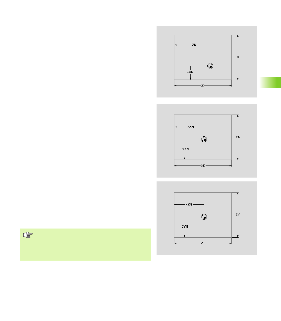
For the main view (see illustration):
Delta X: Dimension of the control graphic window
Delta Z: Dimension of the control graphic window
XN: Position of the workpiece zero point (distance to bottom
edge)
ZN: Position of the workpiece zero point (distance to left edge)
For the front face (see illustration):
Delta YK: Dimension of the control graphic window
Delta XK: Dimension of the control graphic window
YKN: Position of the workpiece zero point (distance to bottom
edge)
XKN: Position of the workpiece zero point (distance to left edge)
For the rear side:
Delta YK: Dimension of the control graphic window
Delta XK: Dimension of the control graphic window
YKN: Position of the workpiece zero point (distance to bottom
edge)
XKN: Position of the workpiece zero point (distance to right edge)
For the lateral surface (see illustration):
Delta CY: Dimension of the control graphic window
Delta Z: Dimension of the control graphic window
CYN: Position of the workpiece zero point (distance to bottom
edge)
ZN: Position of the workpiece zero point (distance to left edge)
TURN PLUS
Adjusts the dimensions to the height and width of the
screen.
Increases the dimensions of the window to show the
complete workpiece.